Back to the Future Markpoon 2015 Jacket Mods

I know it might be a dumb question, but is Marty's jacket in BTTF 2 Nike? I know Doc gives it to him in the Nike Footwear container but I don't believe the jacket has any Nike branding or does it?

Technically yes. Nike actually did design the jacket for the movie. They just didn't put their logo on it.
 
20150210_135033.jpg 20150210_154449.jpg
This is the foam I'm testing to fill the cuffs & waistband. It's from Screwfix in the UK & it's 'flexible', how flexible, I'm yet to find out. I've just tested it on a spare cuff, (for some reason I received 3) so I'll post the results later. It was only £8 but I had to buy a gun applicator which was another £18, fingers crossed it'll do the job!
 
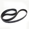
Has anyone thought about using a Timing Belt for the belt and cuffs? I have yet to find an accurate size, but to me it just looks cleaner. You could possibly spray something on it to give a shinny plastic look.
IMG_4976.JPGTiming_belt_retina.jpg
 
To confirm, this method works perfectly, thanks and attached is my one soldered up like you suggested...well kinda, I decided to attach the positive to the speaker as it was easier to solder. Just a side note if your using a 3.5v led bare in mind the voltage of the soundboard is 4.5v (1.5v coin cell batts X 3) so best use a 1/8W resistor.
View attachment 350529

I'm confused :confused where abouts do you solder the LED wires to the speaker & circuit board? On mine there seems to be hot glue covering the connections on both the speaker & button solder points.
 
What LED are you using? I've just ordered some generic flashing LED's. It said they flash twice per second but I think thats too slow. Your's seems to flash just like the one on screen.

Looks like his is a regular 3mm led that is wired to the output of the soundboard. This means that everytime a sound is made, it will light up the LED. It's the same principal that I did by soldering the LED wires to the speaker.
 
Looks like his is a regular 3mm led that is wired to the output of the soundboard. This means that everytime a sound is made, it will light up the LED. It's the same principal that I did by soldering the LED wires to the speaker.

Yep, it's just a basic 3mm yellow LED wired up to the right channel of the sound board. I got the LED at Radio Shack. I just followed jedifyfe's advice and wired the positive and negative terminals to the positive and negative audio pinouts. My board has left and right channels, so I'm using the left channel for the audio and the right channel for the LED.
 
Need some help guys :confused

OK, I'm having some problems wiring the LED to the board. I've got a flashing 3mm LED but now when i hold the wires where they're meant to go it doesn't flash. I'm not soldering it until i'm sure it's in the correct place. The LED is working when i tested it with a cell battery, so I know it's not a fault with that, but it doesn't work on the soundboard.

20150303_122515.jpg
Can someone point out on here where the +/- are meant to go? I've tried the positive on the back of the speaker & the negative where the buttons join the soundboard but nothing happens. I've also tried a number of other combinations.

20150303_122548.jpg

Also, should i pick the glue off the soundboard to get to the solder points first? I'm guessing that's just to protect/strengthen the solder points.
Any help would be greatly appreciated.

(I'm almost about to give up on having the flashing light & just have the sound.) :cry
 
Try connecting the + and - on the LED to the + and - terminal on the speaker. Then, activate the sound. Not sure how this will work with a flashing LED though. With a standard LED, it should pulsate in sync with the audio.
 
The flashing LED is the problem. If you want an LED to flash in sync with the audio, you need to use a standard LED and probably a proper current-limiting resistor (depending on the LED, the audio being used, and the output capability of the amplifier -- this amp might not be able to push enough current to hurt the LED even without a resistor).
 
The flashing LED is the problem. If you want an LED to flash in sync with the audio, you need to use a standard LED and probably a proper current-limiting resistor (depending on the LED, the audio being used, and the output capability of the amplifier -- this amp might not be able to push enough current to hurt the LED even without a resistor).

Scotophor is correct. A flashing LED requires a steady DC current to activate the flashing circuit built into the LED itself.
A normal LED will ramp up to full brightness and back down to off according to which half of the AC signal going to the speaker corresponds to the correct polarity of the LED.
Sound itself is a sine wave, meaning an audio signal is AC, meaning half the time the voltage going to the speaker is going positive from a given reference point, and half the time it is going negative.
During only one half of this full AC cycle, the polarity going to the speaker (and connected LED) will match what the LED needs to light up.
But since a sine wave ramps up to a peak, and then back down, for most of that cycle, the LED will not be fully on because the power will be much lower than the LED needs for full brightness.
Hence my experience leading to my super-bright LED in the waistband being barely noticeable in the daytime. Also, don't forget, the LED is sharing its power with the speaker, so it will be receiving less power than without the speaker attached. jhk1976 has the right idea about dedicating one channel of his stereo sound module just to the LED. Not all sound modules out there are stereo though.
And just a quick FYI for those who are interested, Digital Audio just replicates the sounds natural AC waveform by rapidly switching from full-on to full-off.
By varying both the duration of the on/off times and how often it does it per second (the frequency) you can vary both pitch and volume.
It is a similar principle as to how DC car inverters work. their circuits take the 12DC car power, filter it, amplify it, and then switch it on and off so fast as to give the appearance of 120V AC.

Just my two cents, I hope my errors here have been kept to a minimum.

Your Friend in Time,
--ElectroDFW--
aka David M.
aka Marty McFly Dallas Cosplay
http://www.facebook.com/mcflydallas
 
Has anyone thought about using a Timing Belt for the belt and cuffs? I have yet to find an accurate size, but to me it just looks cleaner. You could possibly spray something on it to give a shinny plastic look.
View attachment 443706View attachment 443707

I did use timing belts at first for mine. Lets just say that they'll make do until you're able to get some of the molded ones, or plastic bellows from chair backs. I feel *SO* much better about my jacket since I switched the timing belts out for the bellows. Just scour garage sales, swap meets and thrift stores and pretty soon you'll have enough for many jackets.

Your Friend in Time,
--ElectroDFW--
aka David M.
aka Marty McFly Dallas Cosplay
http://www.facebook.com/mcflydallas
 
Many thanks guys. :D I figured out that the flashing LEDs were the problem. My original 5mm LED (that didn't flash) does infact now flash in sync with the audio! Only thing is, I damaged the soundboard by picking off the glue covering the solder points :cry Another 2 boards ordered from Big Dawgs greetings, (just in case I screw up again), now I just have to wait 2 weeks for them to arrive....
 
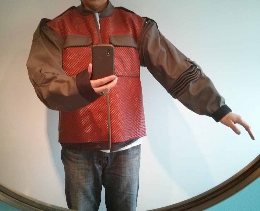
I took the plunge and altered my own jacket. First thing on the list was to shorten the upper arm.

I removed 2 inches from the bicep area near the elbow bellows. I seam ripped the stitches and opened up the length seam.
AWEOZdmwDWWi8xGU_huqWiQd5BaPkfWLG2gZbgtM-Cv0=w1005-h754-no


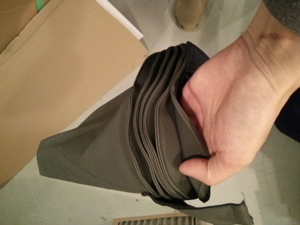
Unfortunately, there was not a lot of material on the upper bellows, so I had to do some intricate stitching.
IMG_20150327_205623.jpg


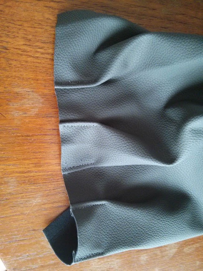
I've added some pleats to the lower sleeve wrist area. Couldn't do this until the biceps were shortened.
IMG_20150328_150342.jpg


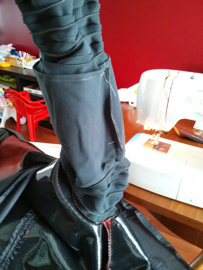
Reattached the lower arm to the bicep
IMG_20150328_152927.jpg


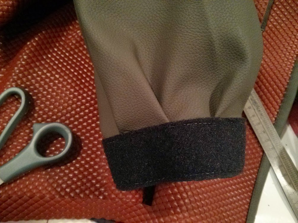
I sewed loop velcro to the cuff to attach the chair seat back ribbing. I think this is way easier than stitching or using the foam.
IMG_20150327_205709.jpg


The sleeve on the left is unaltered from Markpoon
IMG_20150327_135122.jpg


Sleeve on the right has the lower arm reattached to a shorter bicep
05PrzbLKuoGyJJx4fRomEDRtSpVMdftj-GJBHDZlU7Ji=w1005-h781-no


Finished right sleeve with pleats! Looks just like the screen used in shape.
IMG_20150327_135110.jpg


I've already done the other sleeve. I am now shortening the waist to belt height and also adding some pleats. I think it makes the jacket look way better.
 

Your message may be considered spam for the following reasons:

If you wish to reply despite these issues, check the box below before replying.
Be aware that malicious compliance may result in more severe penalties.
Back
Top