Correcting the Lunar Models 41" Excelsior

Dorsal assembly in-progress images.

The entire assembly is scratch-built. However, the inserts in the front of the dorsal will be 3D printed.

Cutting the styrene by hand.

0629172318a-1.jpg


0703170016.jpg


41 plates were cut. More than half that didn't quite make the grade were relegated to being trimmed down to be the spacer plates.

0707172022-1.jpg


The Large plates and Spacer plates were clamped together for sanding to unify their shape.

0707172058.jpg


The Upper Adapter that attaches the dorsal to the primary hull is framed in styrene...

0714170352-1.jpg


0714171012-1.jpg


... then shaped with Apoxie Sculpt.

0714171024a.jpg


0714171040.jpg


Here, the ruffed out parts are stacked unglued at this point to check for alignment.

0715170108a-1.jpg


0715170108b-1.jpg


0715170110-1.jpg


0715170109b-1.jpg


Clean-up of the individual plates and the cutting of the two forward ports is the next step.

Thanx for lookin'!

Tracy
 
Work on the dorsal section continues...


I assembled in 3 sections. The reasone is to keep the Torp recess section separate until I determine how big to cut the opening for the 3D rendered Torp Launchers.

The lower section, the Torp Trench section, and the upper/Adapter section.

0809171328-1.jpg


Here they sit stacked.

0809171327-1.jpg


Further work on the adapter is being done. The addition of styrene to fill where the saucer trench passes over the dorsal assembly. I roughed out the shape of the trench 'blocks', then applied a thin layer of Apoxie Sculpt and allowed it to set up. I then pressed the Adapter into the bottom of the primary hull to cast the profile of the trench. Once fully cured the excess was sanded away and polished to check for flaws.


Top View

0809171330-1.jpg


Bottom view.

0809171331-1.jpg


Side View

0809171331a-1.jpg


The top section of the Dorsal Assembly test fit into the bottom saucer's master.

0809171336-1.jpg


0809171340-1.jpg


Once Bob "Aptiviaboy" Morgan has finished modeling the Dorsal Canon parts, I'll order them printed from Shapeways. Once I receive them, I can then determine how wide to cut the ports into the mid-section of the Dorsal Assembly.


Tracy
 
Last edited:
Plastic Stacking in another section of the ship is complete. This is the Conduit Blister between the Warp Nacelles.


A slab of Resin inaccurately portraying the base of the blister is removed.

0728170255.jpg


0728170255a.jpg


7 plates... 3 large, 4 small spacers are cut from .7mm thick sheet styrene.


0809172256.jpg


Spacer plates are made after holes are drilled through all plates so they can be stacked on a jig for assembly alignment.


0810170128.jpg


Large plates and spacers.


0810170139.jpg


After plates assembled on a jig with the Conduit Blister.


0810170217-1.jpg


Tracy
 
More work in progress to the dorsal.


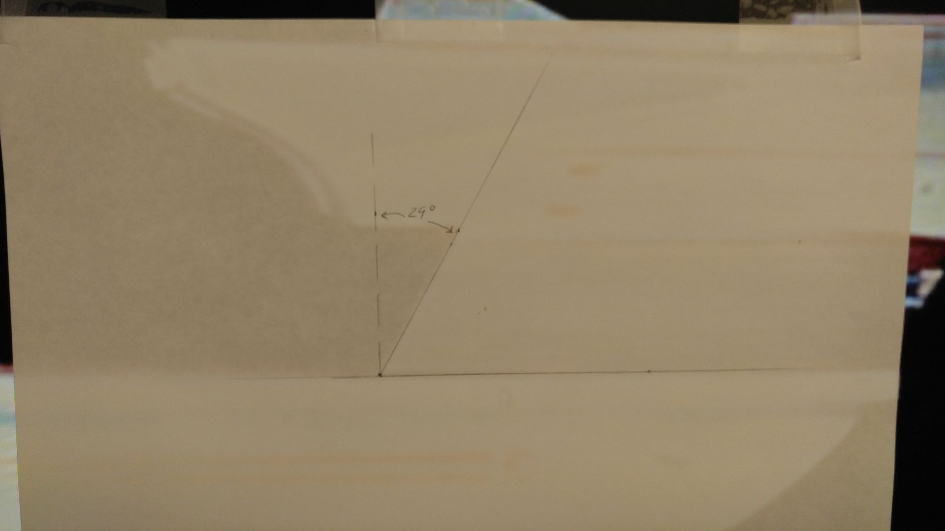
Determining the dorsal's lean angle using images of the studio model.... I have an earlier measurement of 31 degrees on another image, 29deg on this one. More than likely due to slightly different perspectives, so I "meaned" it out to 30 deg.


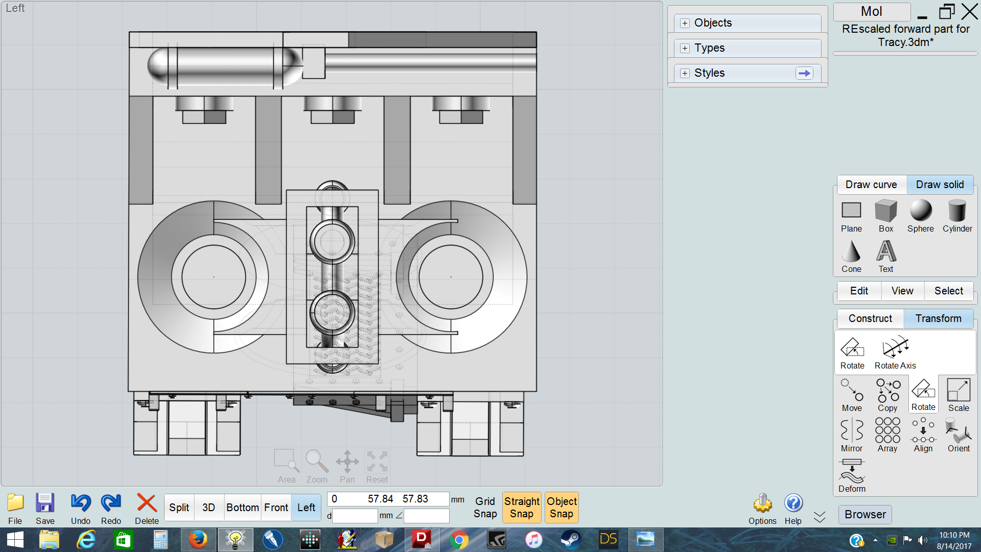
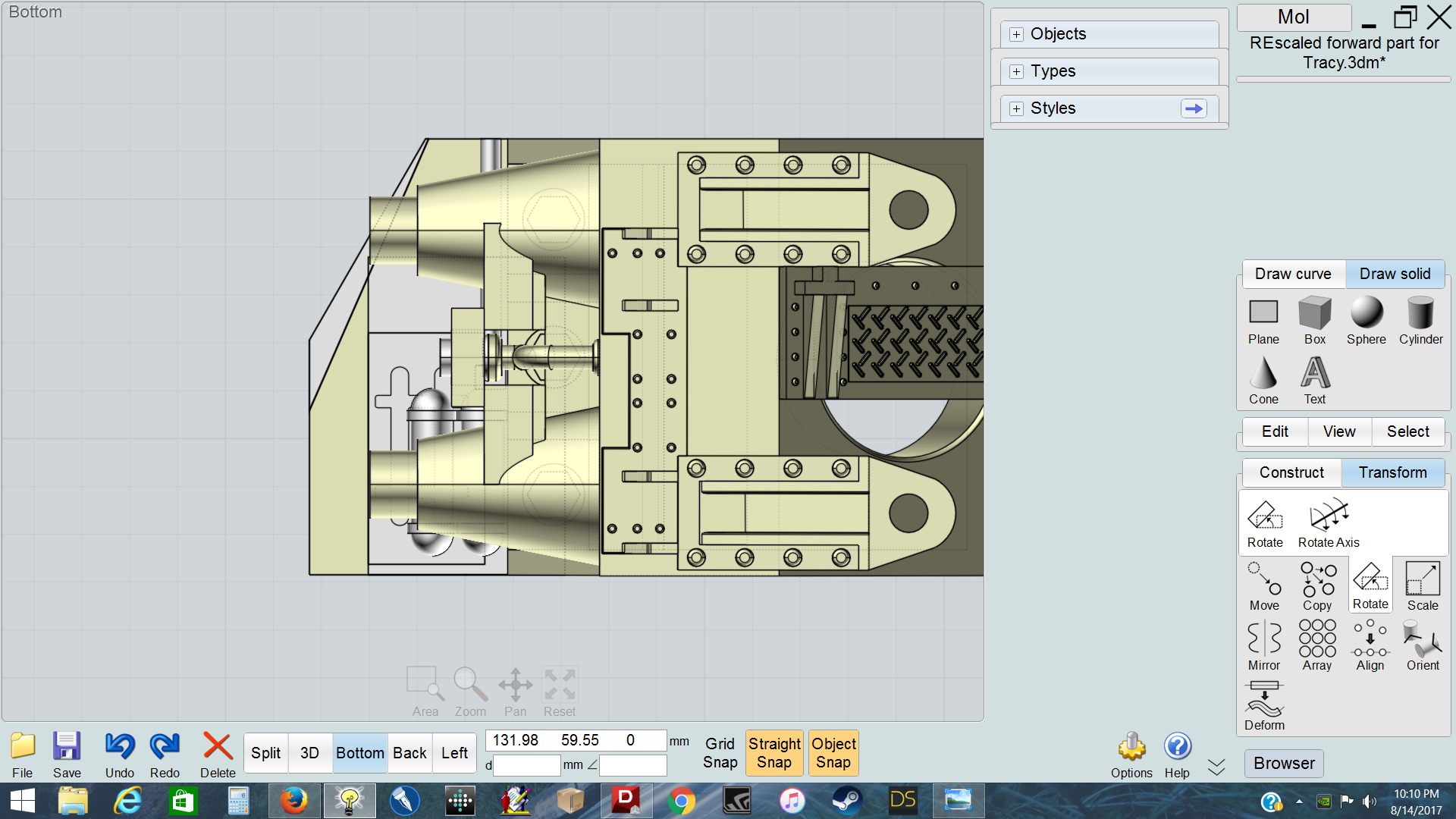
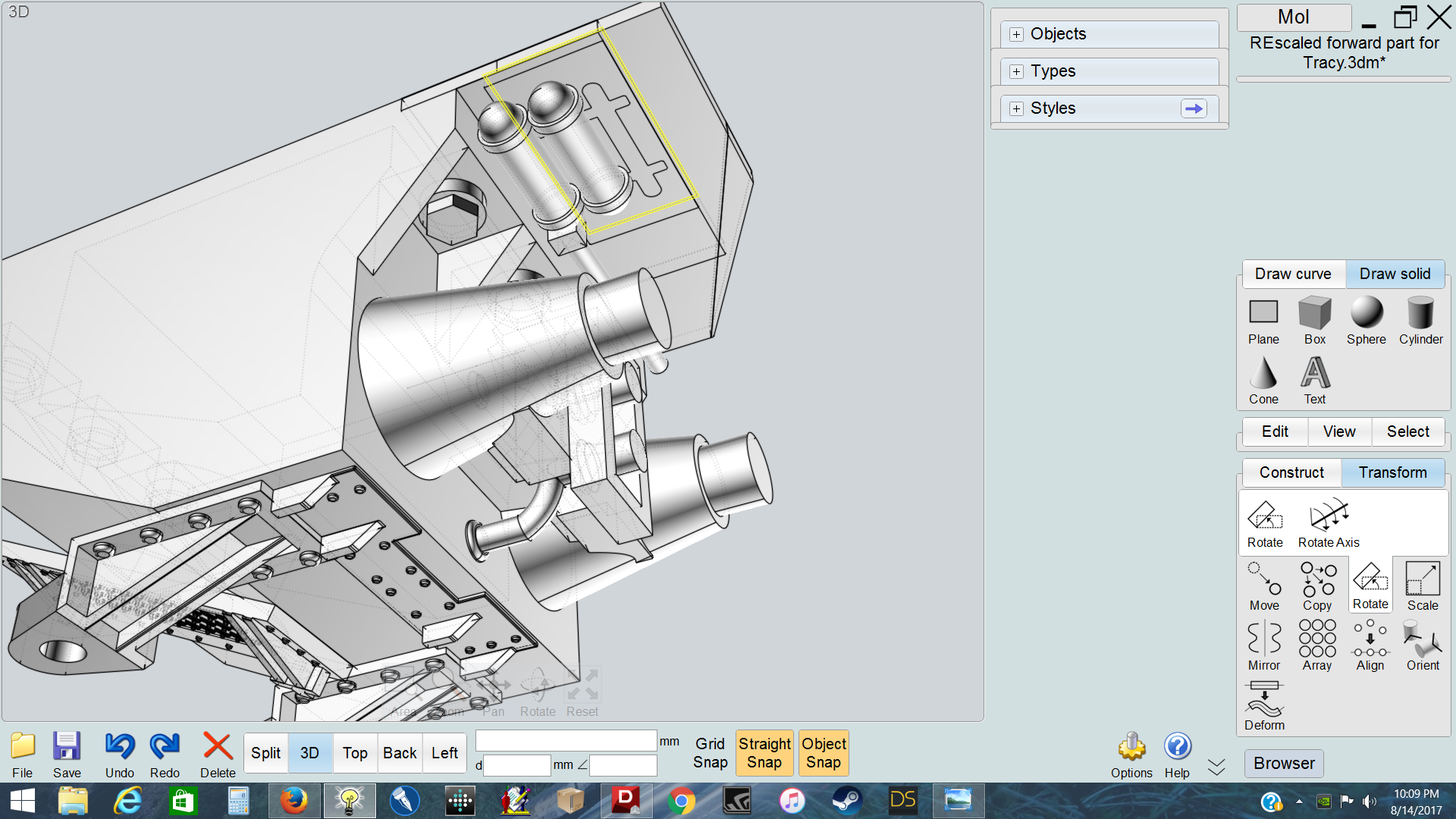
Work on the Torp Launcher inserts is almost done. Much coordination between me, and Bob "Activaboy" Morgan.


Studio model...


3D model images


front


upside down side view


right side up oblique


Tracy
 
Small update while waiting for the 3D Dorsal Torpedo Launchers to show up.


Wrapped up the final stages for the master of the lower half of the Primary Hull. Added the aft bottom plate the saucer's superstructure under the impulse engines will glue down to.


0823171315.jpg


There is a raised paneling detail that covers this section and surrounds the dorsal adapter to the saucer outside the radius of the ring trench. Here the paper template is in place.


0824170131.jpg


The thick plate detail is in place, but further refinement to the part is still needed.


0824170337.jpg


Once the 3D printed dorsal canons arrive, I can finish up assembly of the entire dorsal section and do the final sanding to shape.


Tracy
 
Last edited:
The Dorsal stack is finished then sanded to its final shape.


0826171310.jpg


The 3D printed Torp Launchers are finalized and given a light primer coat with some light dry brushing to pop the detail.


0921170326-1.jpg


The Nacelle grills are next!


Tracy
 
Making the Nacelle grid process.

One big piece of .7mm sheet styrene. Each nacelle has 17 plates (8 Large, 7 smaller spacers) for a total of 34 plate to hand cut.

0828172245-1.jpg


Strips were cut for ease of handling each plate.

0828172251-1.jpg


Holes were drilled through all the plates to accommodate an assembly jig to ensure alignment.

0909171101.jpg


Plates are stacked to test alignment and sand to shape.

0909171108.jpg


0914170923-1.jpg


Once they are sanded to shape, the plates that don't cut the mustard are designated to be trimmed down as spacer plates.

0907170026.jpg


0907172257-1.jpg


0914170313.jpg


Once the spacer plates are all trimmed, they go back on the jigs to be sanded down to "their" final shape.

0914170923-1.jpg


Once the spacers are finalized, everything goes on the port and starboard jigs to test shape and alignment.

0914171120-1.jpg


To save some weight, I desided to "core out" the plates by removing material down their longitudinal axis by drilling holes just inside the end jig dowels, then cutting away at the edges of the holes.

0915171633.jpg


Once all the plates were cored, they are stacked and glued together on their respective jigs, after some set time they were removed and clamped to a flat surface (my drafting table) with a piece of wood to ensure a flat assembly sporting no waves in the grill.

0915172129-1.jpg


It took 85 individual plates to reproduce this interesting characteristic of the Excelsior Class.

0916171058.jpg


Now back to modifying other parts of the kit for improved accuracy...

To Be Cont....

Tracy
 
Last edited:
You are insane and a master of your craft. This is so beautiful... (My only nit is that the neck greeblies are part of the deflector array -- the forward torpedo launchers are the semi-recessed greeblies around toward the sides of the "gunwales", the slightly wider bit at the top of the secondary hull.)

I so wish there were a 1:350 Excelsior. But this is some nice vicarious enjoyment of the next best thing.

--Jonah
 
Yeah, some fan sites have called them that. In Generations, the E-B had one open like a door with Work Bees flying in and out of what is called a cargo bay in the dorsal.

I call them Dorsal Torp Launchers because that's what ILM called them.

Tracy
 
Images of how the secondary hull were fix aren't shown here. Here ya go!

Determining the shape of the bow of the secondary hull using scaled images.

20131129_153201.jpg


The correct profile is re-inforced to help maintain its shape.

20131129_142035.jpg


The original hull piece is cemented to the new profile. You can see the difference here.

20131130_213106-1.jpg


Apoxie Sculpt was used to reshape the bow just like the nacelles seen earlier.

20131201_040814-1.jpg


The step in the fantail was misrepresented with a swoop instead of a step. Here the flaw is cut away.

20131129_025417-1.jpg


Strip styrene was glued into place to create a better gluing surface for the new skin.

20131129_035030-1.jpg


New skin is in place, then filled and sanded.

20131130_213320-1.jpg
.

Multiple sessions of filling and sanding the new master took place to ensure a smooth and accurate shape.

20131207_151930-1.jpg


The master is primed.

20131202_232409-1.jpg


Now creating the lip in the bow... It is the same height as the thickness of the fantail.

20131210_010410-1.jpg


A mold was built with 90deg braces to ensure a virticle wall.

20131210_022644-1.jpg


The secondary hull master was coated with mold release and placed into the mold, then resin was injected into the mold..

20131210_105712-1.jpg


The hull was removed, then the resin was flat sanded down to the mold.

20131210_115454-1.jpg


The new lip was removed from the mold and cleaned up.

20131210_142144-1.jpg


Then it was glued into place, then filled, sanded, and blended into the secondary hull master.

20131210_173013-1.jpg


Some adjustments were made, then finally checked to a scale image of the studio model's secondary hull.

20131223_173205-1.jpg


20131223_173227-1.jpg


Tracy
 
You are doing an awesome job with this build. I had, at one time, two of these kits. I never got close to what you are achieving now. Looking forward to more updates and seeing the final results. :)
 

Your message may be considered spam for the following reasons:

If you wish to reply despite these issues, check the box below before replying.
Be aware that malicious compliance may result in more severe penalties.
Back
Top