You are using an out of date browser. It may not display this or other websites correctly.
You should upgrade or use an alternative browser.
You should upgrade or use an alternative browser.
SW – ANH (5 Foot) - Studio Scale Millennium Falcon Build
- Thread starter vfxsup64
- Start date
Gort: If it wasn't for your thread as well as the many others here and the contributors therein, I could not have come as far as I have, so far.
I really appreciate this forum and the collective knowledge, expertise, talent and giving spirit that resides here.
Thank you very much for the kind words of encouragement!
Regards,
Andre
- - - Updated - - -
batguy: Thank you!
ChrisGFX: Thank you! But, yes..the build awaits...:eek
I really appreciate this forum and the collective knowledge, expertise, talent and giving spirit that resides here.
Thank you very much for the kind words of encouragement!
Regards,
Andre
- - - Updated - - -
batguy: Thank you!
ChrisGFX: Thank you! But, yes..the build awaits...:eek
joberg: Indeed, the curve of the hull is to me, one of the critical 'gestures' of the overall design. It ties so many other things together...
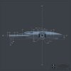
While deriving the radius and y-axis offset measurement of the hull domes, I assumed that three key points were on a constant radius intersecting the following points:
1) 2 docking ring wall intersections - on the X-axis
2) One of the outer turret ring contact points - on the X-axis.
That establishes the beautiful curved line intersection running through the X-axis of the ship and the subsequent Z-Axis upper/lower jaw box intersections with same hull curve/surface.
With respect to the cockpit not quite fitting in the SW shot, to my eye the wire frame circle looks a little too screen right to where it would line up to the center line of the cockpit. The circles don't quite line up concentrically, in perspective.
It's subtle - but of some concern. I think it's mostly lens distortion, but the Wankel donor kit part, may tell all...
apb
Last edited:
Stu:
Thank you for the feedback! I appreciate it.
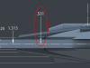
Yes, the cockpit...I feel it is just a little too close to the mandible - maybe as much as a 1/4" - perhaps more. The Wankel will be the key measure, so long as I place it correctly along the length of the mandible wall. I will be laying out the AMT truck, Panther G, Bandai 8 ton and Sealab parts to check the overall mandible length and then see how the Wankel sits and then check the overall cockpit placement. Always a good idea to return to the donor kit parts as a double check!
As for the large rear underside landing gear box ends - this is an area I'm not too clear on. I have very little photo reference that corroborates completely and I was throwing a few "Hail Marys" so to speak. Any additional data would be much appreciated and I'll update the prints and post them when ready (look for a PM).
With respect to the turret window outer rim diameter, I get 4.50 inches.
As for the upper/lower jaw box angled length, I'll have that to you soon, as well.
Thanks again!
Regards,
Andre
Thank you for the feedback! I appreciate it.
Yes, the cockpit...I feel it is just a little too close to the mandible - maybe as much as a 1/4" - perhaps more. The Wankel will be the key measure, so long as I place it correctly along the length of the mandible wall. I will be laying out the AMT truck, Panther G, Bandai 8 ton and Sealab parts to check the overall mandible length and then see how the Wankel sits and then check the overall cockpit placement. Always a good idea to return to the donor kit parts as a double check!
As for the large rear underside landing gear box ends - this is an area I'm not too clear on. I have very little photo reference that corroborates completely and I was throwing a few "Hail Marys" so to speak. Any additional data would be much appreciated and I'll update the prints and post them when ready (look for a PM).
With respect to the turret window outer rim diameter, I get 4.50 inches.
As for the upper/lower jaw box angled length, I'll have that to you soon, as well.
Thanks again!
Regards,
Andre
Missed a dimension...


So, I'm going to guess 1/4" formed plexi for the actual hull domes - the remaining thickness, plywood laminate ring structure.
But I'm just guessing...")
Regards,
Andre
So, I'm going to guess 1/4" formed plexi for the actual hull domes - the remaining thickness, plywood laminate ring structure.
But I'm just guessing...
Regards,
Andre
Attachments
Last edited:

jawsmodels
Sr Member
Andre,
you are a true champ for sharing your work like this.
Very inspirational for all.
Keep up the fantastic work.
Theres going to be a few more falcons getting built from your work mate.
Cheers
you are a true champ for sharing your work like this.
Very inspirational for all.
Keep up the fantastic work.
Theres going to be a few more falcons getting built from your work mate.
Cheers
maruska
Sr Member
This a absolutely brilliant! Thanks for doing this Andre! I've been contemplating making a half scale 5' falcon - which is different than the 32" ESB version. Most of my research was around the ESB model - and the 2d drawings I've posted are based on the 32 inch-er. This is a great amount of work! I look forward to working more together.
Cheers,
J.
Cheers,
J.
Last edited:
Maruska: You are welcome!
Which reminds me...my master photoshop blueprint files for each view were intentionally set up in real world inches at 100 dpi (8400 pixels by 8400 pixels) - that made dimensioning much easier as I only needed to snap and drag lines to even fractions of 1" grid squares.
So, the full size "5-foot" blueprints, including title block and dimensions, if printed full size and at 100dpi, would generate an actual piece of paper that is 84 inches or 7' square! That could be printed but would be rather unwieldy on a work bench (although that depends on the size of one's workbench!).
But, if one wanted to print the blueprints out for a 1/2 scale "5" footer...that would only by a print about 3.5 feet square. Quite a bit more manageable on mot benches for cross-section templating, scratch built and/or donor kit part layouts etc...
Do you know if there is a place on theRPF that I could warehouse these so anyone who wanted the big files could download them? I would update them as tweaks and changes needed to be made but it could be a central dynamic repository...
Regards,
Andre
maruska
Sr Member
Do you know if there is a place on theRPF that I could warehouse these so anyone who wanted the big files could download them? I would update them as tweaks and changes needed to be made but it could be a central dynamic repository...
I'm not sure if there is a file size limit on attachments here, but it's what I've been using GrabCAD for, essentially. You can upload 2D files as easily as 3D, so it might be a good route to go.
You're rendering in Modo, right? Does Modo do any type of vector output? Making these into a PDF would reduce the size dramatically - wouldn't look as pretty without the shading, but could be more useful.
J.
Maruska,
Thank you for the suggestion - I'll check things out over at GrabCad.
I am lighting and rendering the base surfaces out of Modo and I believe the only 'vector' renders available are for vector motion blurring in a 2D composite.
Unfortunately, I did all of the subsequent dimensioning and line work in Photoshop when I should have just started originally in either Illustrator (which I would need to learn and get into) or a proper CAD system - which I now have and am working on drafting some subassemblies with - I should probably just do the whole thing in either a CAD system or a solids modeler, moving forward).
While the renders are nice on the eyes, I've painted myself into a bit of a corner...:facepalm
Regards,
Andre
Last edited:
maruska
Sr Member
LOL - been there.
Actually I'm still there. There have been so many points where I've thought - shoot, I really should have done X this way... next time. The cockpit sidewalls I just finished took forever and there were surly more efficient ways of doing things in hindsight. Live and learn.
GrabCAD is essentially just a big repository for all things 3D and documentarian (is that a word?). If you're planning on releasing stuff into the wild anyway, it's a good place to go and a managed third party (which is nice when my own website is down)
What CAD software are you getting up on? I'm doing most of my stuff in Alias and Solidworks.
J.
LOL - been there.
What CAD software are you getting up on? I'm doing most of my stuff in Alias and Solidworks.
J.
This will date me a bit but I started, back in the day, on Cadkey. Long gone now in its original form but I used it exclusively when I was design engineering at Boss Film and Digital Domain. It was robust, fast and we shot stuff out to CNC all the time. But that was then and this is now...
I'm currently doing some stuff in DeltaCad which is ok but I'd love to work in either Solidworks, Rhino (on a Mac) or even AutoCad.
But, I've also been looking at Inventor Fusion. Trying to keep the number of apps I need to use for drafting, sculpting, solids modeling and RP prep to a minimum!
Regards,
Andre
Hah! Yes, look for something on that end of next week. ;-)
In truth, I have thought about that kind of project for the future. What would be interesting is to consolidate and then scan, sculpt, model etc. all of the necessary donor kit parts in 3D - (these should probably be curated anyway for the future). Many of these kits kits are getting rare as hen's teeth.
Then rapid prototype them 1/2 scale for a SW ANH '32 inch' version. Not all parts would need to be RPd, of course. Many could be scratch built to scale as needed, desired etc.
Certainly a herculean task for one person but distributed amongst a team of enthusiastic people....many hands make light work.
Regards,
Andre
Sent from my iPad using Tapatalk HD
Similar threads
- Replies
- 4
- Views
- 576
- Replies
- 55
- Views
- 8,010