You are using an out of date browser. It may not display this or other websites correctly.
You should upgrade or use an alternative browser.
You should upgrade or use an alternative browser.
Star Wars movie set den build
- Thread starter Amazing DJ
- Start date
Amazing DJ
Well-Known Member
Christmas Eve, working on this project a little more. Here, I have flipped the thin hardboard window covering over to the "blank" side. I'm adding metal plates for the magnetic catches. Four of them are shown here, as I prepare to glue them on with Liquid Nails construction adhesive.

Here is a look down the edge of my den window frame. It has 3 (brown) magnetic catches screwed to the inside of the frame.

The whole 4 x 8 window decoration should just snap into place. Now I'm off to go shopping for some black roller shades...
Here is a look down the edge of my den window frame. It has 3 (brown) magnetic catches screwed to the inside of the frame.
The whole 4 x 8 window decoration should just snap into place. Now I'm off to go shopping for some black roller shades...
Amazing DJ
Well-Known Member
On Christmas Day, I give you a video. This shows the underguts of my lighted chair mat. I have a 6" tall platform where my desk sits, covering about a third of my room. Under the platform, I added a string of RGB LED's that is remotely controlled to any color or brightness. Over the top of that is a wooden hatch, a white Imperial logo disc, and (not shown) I added a polycarbonate clear chair mat to protect the vinyl on the logo disc. I know you like to see how things work. So this video shows what's "under" the floor.
VIDEO --> VIDEO: Lighted Chair Mat <- How it's made
VIDEO --> VIDEO: Lighted Chair Mat <- How it's made
Even though it is a circle of LED's around the edge, the light really shines evenly throughout the whole pattern, even in the middle.
:cool
:cool
Amazing DJ
Well-Known Member
I attached the unfinished Falcon window covering to see how it would look behind my U-shaped desk. This image is HEAVILY HEAVILY edited. I blacked out the existing mini-blinds. The desk is under construction too, and is partially covered up with pink masking paper at the moment. Looking at the unfinished window covering, I think it looks too much like a wooden wagon wheel. I have some ideas to improve the paint job on it. Graphical mock-ups serve their purpose!

What would YOU do to improve it? One thing my wife suggested... move the black stereo out of the middle of it. Okay...
What would YOU do to improve it? One thing my wife suggested... move the black stereo out of the middle of it. Okay...
First... LOOKS FANTASTIC!!!!! The window turned out really nice!
For all intent and purposes... that "specific" window is associated with only one ship... the one one ship we've all grown to love!") Putting anything other than the outline of the console, the cockpit or the characters would seem out of place if not get lost with whatever is in front on the window - if that makes sense.
Putting anything other than the outline of the console, the cockpit or the characters would seem out of place if not get lost with whatever is in front on the window - if that makes sense.
The only thing I can think of off hand would be to remove the top shelf? The window gets lost behind not only the stereo but also the curve of the shelf.
Another idea... would be to create a new "ship" window other than the MF?
That's just my two cents and please DO NOT think I'm taking anything away from the great work you've done so far!
For all intent and purposes... that "specific" window is associated with only one ship... the one one ship we've all grown to love!
Putting anything other than the outline of the console, the cockpit or the characters would seem out of place if not get lost with whatever is in front on the window - if that makes sense.The only thing I can think of off hand would be to remove the top shelf? The window gets lost behind not only the stereo but also the curve of the shelf.
Another idea... would be to create a new "ship" window other than the MF?
That's just my two cents and please DO NOT think I'm taking anything away from the great work you've done so far!
jme3
Sr Member
Another idea... would be to create a new "ship" window other than the MF?
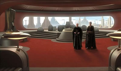
Yeah, like maybe the Star Destroyer windows or, as the desk is quasi reminiscent of the computer stations in the Emperor's throne room, how about the windows from the throne room? Both of those windows are 2D affairs that might lend themselves more easily to this application.
Amazing DJ
Well-Known Member
Your suggestions are very much appreciated. As you may have guessed, my den is not made to fully replicate a specific ship interior or a full specific set. It contains a mix of the design elements that I admire the most. And all that must be constructed so the room can still be functional for daily use as an office and voice recording studio. There must be desk room for a computer, 3 monitors, a printer, a flatbed scanner, sound equipment, and all the other computer peripherals. So I'm stuck with a shelf.
I already have a 2nd window in mind for the back wall of the room. What is cooler than looking out and seeing the Death Star? How about this design?
VIDEO: -> back_wall-death_star.mov <-
I'm most unsure about how to frame the Death Star in this window. The frame (shown) is not a copy of any specific window, but I would entertain changing this one to a more snazzy window frame, given a screen capture. Got any?
jme3
Sr Member
I already have a 2nd window in mind for the back wall of the room. What is cooler than looking out and seeing the Death Star? How about this design?
VIDEO: -> back_wall-death_star.mov <-
I'm most unsure about how to frame the Death Star in this window. The frame (shown) is not a copy of any specific window, but I would entertain changing this one to a more snazzy window frame, given a screen capture. Got any?
Yeah, the DS image would be cool.
My vote on the windows would be those alternating/inverted triangle windows from the Star Destroyer bridge. I do like the Emperor's throne room window(s) as well, though that would necessitate a view other than the Death Star since those windows are on the Death Star and you wouldn't be getting the same perspective...
Amazing DJ
Well-Known Member
My split Star Wars door is complete. I have photos of the whole idea/construction process. The idea was to dress up a closet door and build it out of recycled materials I already had in my garage. I whipped up this design in Google Sketchup. It fits the proportions of my skinny door and has some design elements from the movie. One thing is for sure - it's not something the average person would have in their home!

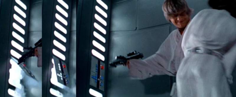
My door is based loosely on one of these cool doors in the movie, below.

Who doesn't like those lighted oval shapes on the sides, wow! If I can't duplicate all the parts of this movie set, I at least want to get the ovals correct, as they set it off.
The closet door itself isn't too exciting at first. But it was easy to mark it up with some different colors of masking tape and take some measurements. At this point I hadn't ripped off the door handle yet. I do like to tape up a paint color palette and figure out what would look good. I have already painted some of the edge trim which will eventually make it look like the door halves come out of side pockets.

I have decided that I'm making a doorframe lightbox that will NOT be attached to the wall or door. It will be engineered to plug over the top of everything, yet look like it is a part of the door setup. This decision made it easy to carry the lightbox assembly back and forth to the garage for work. Below, I am fitting the base. It slides under the existing door.

I whipped up a frame out of 2x2's and attached the top plate (MDF) and the bottom plate (MDF). I wanted a sparse frame - to leave room for the largest light openings I could get. The frame pieces are wood glued to each other and held together with drywall screws. Below, I have carried the lightbox frame in from the garage and fit it over the doorway in my den.

Online, I found someone's design for oval light shapes. Yeah, their proportions look right.

So I drew up some of my own ovals in Paint Shop Pro. Then they were printed on card stock and the holes were cut with an X-acto knife. The template below would be used to make 64 oval holes exactly matching.

Unless you've ever tried to cut 64 identical holes equally spaced in hardboard, you don't know what physical and mental torture is! A Dremel tool helps here. This was the most time-consuming task, cutting, sanding, primering, filling, topcoating these holes so they would look identical.

Below, I had cut the first 6 holes and was testing lights with a piece of foil behind that for reflectance. The finished light reflector would be more sophisticated than this. I eventually made it out of a 4" PVC pipe which was cut in half lengthwise. The white lenses are white Acrylite from a sign supply company. They normally come in 4x8 foot sheets, but you can sometimes dig through their partial sheets and negotiate a discount.

I have 10 more photos later, if you like this?
My door is based loosely on one of these cool doors in the movie, below.
Who doesn't like those lighted oval shapes on the sides, wow! If I can't duplicate all the parts of this movie set, I at least want to get the ovals correct, as they set it off.
The closet door itself isn't too exciting at first. But it was easy to mark it up with some different colors of masking tape and take some measurements. At this point I hadn't ripped off the door handle yet. I do like to tape up a paint color palette and figure out what would look good. I have already painted some of the edge trim which will eventually make it look like the door halves come out of side pockets.
I have decided that I'm making a doorframe lightbox that will NOT be attached to the wall or door. It will be engineered to plug over the top of everything, yet look like it is a part of the door setup. This decision made it easy to carry the lightbox assembly back and forth to the garage for work. Below, I am fitting the base. It slides under the existing door.
I whipped up a frame out of 2x2's and attached the top plate (MDF) and the bottom plate (MDF). I wanted a sparse frame - to leave room for the largest light openings I could get. The frame pieces are wood glued to each other and held together with drywall screws. Below, I have carried the lightbox frame in from the garage and fit it over the doorway in my den.
Online, I found someone's design for oval light shapes. Yeah, their proportions look right.
So I drew up some of my own ovals in Paint Shop Pro. Then they were printed on card stock and the holes were cut with an X-acto knife. The template below would be used to make 64 oval holes exactly matching.
Unless you've ever tried to cut 64 identical holes equally spaced in hardboard, you don't know what physical and mental torture is!
A Dremel tool helps here. This was the most time-consuming task, cutting, sanding, primering, filling, topcoating these holes so they would look identical.Below, I had cut the first 6 holes and was testing lights with a piece of foil behind that for reflectance. The finished light reflector would be more sophisticated than this. I eventually made it out of a 4" PVC pipe which was cut in half lengthwise. The white lenses are white Acrylite from a sign supply company. They normally come in 4x8 foot sheets, but you can sometimes dig through their partial sheets and negotiate a discount.
I have 10 more photos later, if you like this?
Attachments
Amazing DJ
Well-Known Member
Yesterday I posted the first 10 pics of a doorway under construction, recently completed. Today, here's another 10. Here, I am gluing and clamping the hardboard over the lightbox frame. The thin hardboard is attached with wood glue, and with tiny screws which are countersunk and filled with wood filler. The screws are essential, because if I used little trim nails, they tend to back themselves out and ruin the paint finish later.

This part was a blast to work on! I made an MDF covering for the existing doorway. It is split in the middle using an unusual pattern. Then it was trimmed out with composite wood and a circle made of hardboard. Both happen to be the same thickness, so I got a pattern with no seams. Here, I have begun fill in the seams, first with wood filler, then with red spot filler. You can make anything smooth with spot filler and Kilz primer.

Below is more detail painting on the door covering. Both halves fit together like a jigsaw puzzle. In the background is a clear-ish lens cover I'm fabricating for the top "crown" of the doorway.

I used this photo in a previous post to show how bright the LED light is inside this frame. The LED strips are laid inside 4" PVC pipe which has been halved and covered in a foil metal shiny tape.

TESTING! The Star Wars doorways always used white lights. But, Oh wow, I can turn these any color with the flick of the remote control.

The whole wiring assembly is laid out on the carpet and checked. Looking left-to-right, we have the left upright tube, then the top crown light, then a backlight box for a simulated control panel, then wired over to the right upright tube. The bottom has an infrared sensor for the remote control. In the final assembly, this sensor will be placed behind the rightside upright lens. Power for the whole thing feeds in at the bottom from a tiny AC adaptor (outside the photo). Wiring was easy. These sections are wired with 4-conductor cable. For servicing, each section can be unplugged from the next. For the plugs, I used commonly available computer power supply plugs and sockets. They use 4 wires for the LED's. There is
1 -> 12 VOLTS
2 -> R for the Red color
3 -> G for the Green color
4 -> B for the Blue color

This is the backside of the lightbox, propped up on the floor. I've got the black and gray paint on it.

Below, I've got the lightbox standing upright, getting ready to swing it into place. This whole assembly does not need screwed to the wall. I designed it so it fits over every dimension of the existing doorway like a glove. In fact, the hardboard was angled slightly so it "grabs" the doorframe edges and snaps on tightly like a snap-together model kit. The door covers are in place. Notice the old doorknob is GONE!

Below is a test-fit of the unpainted lightbox with no covers on it. There are six rectangular covers to be installed. Each one snaps in place with a magnet catch system. At this point in the construction, I have not cut out holes for the control panel yet. I'm moving it to the rightside, one of the few changes from my original Sketchup design. On a budget, my control panel will be made of entirely recycled materials from my shop.

I like the ovals of light. Seems like these movie Stormtroopers might come busting through the doorway at any time!

Next time, I'll post another set of photos, detailing the finished doorway!
This part was a blast to work on!
I made an MDF covering for the existing doorway. It is split in the middle using an unusual pattern. Then it was trimmed out with composite wood and a circle made of hardboard. Both happen to be the same thickness, so I got a pattern with no seams. Here, I have begun fill in the seams, first with wood filler, then with red spot filler. You can make anything smooth with spot filler and Kilz primer.Below is more detail painting on the door covering. Both halves fit together like a jigsaw puzzle. In the background is a clear-ish lens cover I'm fabricating for the top "crown" of the doorway.
I used this photo in a previous post to show how bright the LED light is inside this frame. The LED strips are laid inside 4" PVC pipe which has been halved and covered in a foil metal shiny tape.
TESTING! The Star Wars doorways always used white lights. But, Oh wow, I can turn these any color with the flick of the remote control.
The whole wiring assembly is laid out on the carpet and checked. Looking left-to-right, we have the left upright tube, then the top crown light, then a backlight box for a simulated control panel, then wired over to the right upright tube. The bottom has an infrared sensor for the remote control. In the final assembly, this sensor will be placed behind the rightside upright lens. Power for the whole thing feeds in at the bottom from a tiny AC adaptor (outside the photo). Wiring was easy. These sections are wired with 4-conductor cable. For servicing, each section can be unplugged from the next. For the plugs, I used commonly available computer power supply plugs and sockets. They use 4 wires for the LED's. There is
1 -> 12 VOLTS
2 -> R for the Red color
3 -> G for the Green color
4 -> B for the Blue color
This is the backside of the lightbox, propped up on the floor. I've got the black and gray paint on it.
Below, I've got the lightbox standing upright, getting ready to swing it into place. This whole assembly does not need screwed to the wall. I designed it so it fits over every dimension of the existing doorway like a glove. In fact, the hardboard was angled slightly so it "grabs" the doorframe edges and snaps on tightly like a snap-together model kit. The door covers are in place. Notice the old doorknob is GONE!
Below is a test-fit of the unpainted lightbox with no covers on it. There are six rectangular covers to be installed. Each one snaps in place with a magnet catch system. At this point in the construction, I have not cut out holes for the control panel yet. I'm moving it to the rightside, one of the few changes from my original Sketchup design. On a budget, my control panel will be made of entirely recycled materials from my shop.
I like the ovals of light. Seems like these movie Stormtroopers might come busting through the doorway at any time!
Next time, I'll post another set of photos, detailing the finished doorway!
Attachments

Last edited:
SWEET! I love it! You did a GREAT job on the ovals! Fantastic Job!
Fantastic Job!Amazing DJ
Well-Known Member
In previous posts, I showed 20 photos of my door. Here are the last pics concluding the construction process of the door portion of my room build.
Keeping with the idea of using recycled "found" items for the door, I came across a piece of thick styrene plastic from an old clock face. This would be perfect for making a speaker grille on the leftside of the door frame. There is a paper template on the left which I used for tracing a design onto this old clock face.

In the center is the rough-cut grille with one coat of primer on it. After this photo, I used a Dremel tool to clean it up, along with an X-Acto knife, sandpaper, more primer and spot filler. The final product was perfectly smooth. After some smoothing out, I'd say the part came out looking better than my Google Sketchup drawing. The grille is sitting on a grille cloth. The cloth has a heavy weave, and was recycled from a dark gray office chair fabric.

After a few months of work, the door lightbox is placed against the wall. The 6 covers are now snapped on. A remote control can make it any color, or white, which is technically ALSO a color.

The upper right cover is removed so you can see the guts. Common computer power supply plugs and sockets carry power between the LED RGB strip sections.

I had intended to make the illusion that the door really does split in the middle and open into hidden side pockets. I have added some subtle details courtesy of Hobby Lobby mini-stick-on greeblies aisle.

In this view, you can see the rightside control panel. It is made out of found items as well; a cover off a Borden Wood Putty container, 4 square buttons from a Denon broadcast CD player, a spun aluminum trinket from the front of a 1980's reel-to-reel player, and a blue lens from a dead Fisher FM tuner.

Below, you can see the detail that went into the trim-out.

So there is the door!
Next time, I'll detail my Millennium Falcon-like desk construction here, or show more progress on my MF window covering. I just ordered some LED backlighting for the window covering, so that's going to be pretty interesting. Oh! And I got cupholders to install into the desktop. They are powered, of course, with a 12V blue LED glow! Hey, ya gotta have drinkage in space!
Keeping with the idea of using recycled "found" items for the door, I came across a piece of thick styrene plastic from an old clock face. This would be perfect for making a speaker grille on the leftside of the door frame. There is a paper template on the left which I used for tracing a design onto this old clock face.
In the center is the rough-cut grille with one coat of primer on it. After this photo, I used a Dremel tool to clean it up, along with an X-Acto knife, sandpaper, more primer and spot filler. The final product was perfectly smooth. After some smoothing out, I'd say the part came out looking better than my Google Sketchup drawing. The grille is sitting on a grille cloth. The cloth has a heavy weave, and was recycled from a dark gray office chair fabric.
After a few months of work, the door lightbox is placed against the wall. The 6 covers are now snapped on. A remote control can make it any color, or white, which is technically ALSO a color.
The upper right cover is removed so you can see the guts. Common computer power supply plugs and sockets carry power between the LED RGB strip sections.
I had intended to make the illusion that the door really does split in the middle and open into hidden side pockets. I have added some subtle details courtesy of Hobby Lobby mini-stick-on greeblies aisle.
In this view, you can see the rightside control panel. It is made out of found items as well; a cover off a Borden Wood Putty container, 4 square buttons from a Denon broadcast CD player, a spun aluminum trinket from the front of a 1980's reel-to-reel player, and a blue lens from a dead Fisher FM tuner.
Below, you can see the detail that went into the trim-out.
So there is the door!
Next time, I'll detail my Millennium Falcon-like desk construction here, or show more progress on my MF window covering. I just ordered some LED backlighting for the window covering, so that's going to be pretty interesting. Oh! And I got cupholders to install into the desktop. They are powered, of course, with a 12V blue LED glow! Hey, ya gotta have drinkage in space!
Last edited:
Similar threads
- Replies
- 18
- Views
- 1,471
- Replies
- 2
- Views
- 549
- Replies
- 0
- Views
- 321