oldskool
New Member
Hi all!
I started this build about a month ago in preparation for a costume party coming up. I've always wanted a Darth Vader costume since I was a kid, so I'm kind of thrilled to be part way there!
I started by purchasing a Rubies plastic helmet, and a 'full' costume (to take care of the cape and the rest) from here.
I used a lot of guides/reference material from the Sith Training Temple [STT].
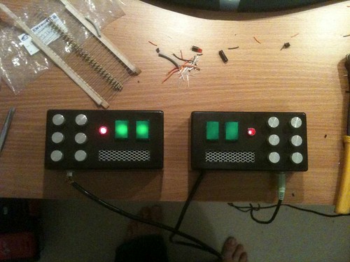
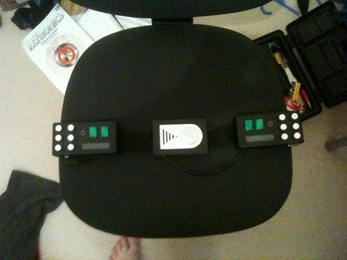
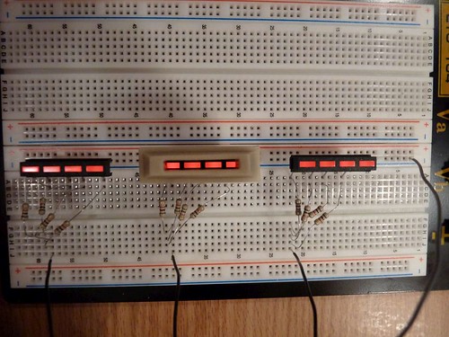
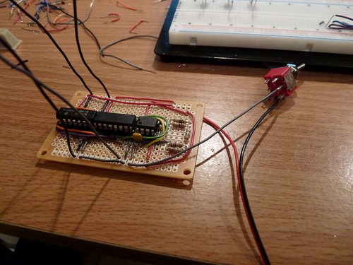
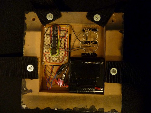
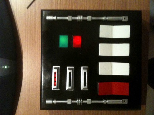
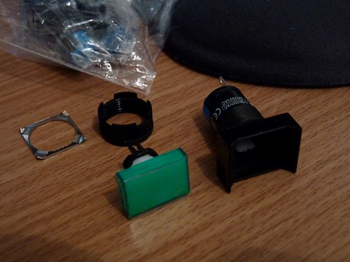
I decided I would make the belt boxes and chest box with full lights to make it look more authentic (and a whole lot more awesome) -- as well as being a means of 'starting' on my way of creating a full costume.
NB:
This is most likely not going to be 'screen accurate'. I have a lot of respect and admiration for those who spend the time (and, where applicable, the money) to create detailed and accurate recreations of the Darth Vader costume. I just want a costume that will look good, and be recognised as being 'good enough'")
Part 1: Chest Box [CB].
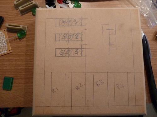
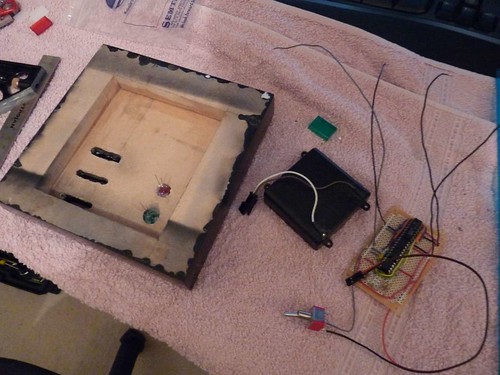
A lot of the guides / tutes I saw had chest boxes being moulded, or made from fibreglass. I've got more experience with wood, so I decided to make the CB from wood. Originally, I was going to do like darienvader did with his own chest box (http://www.therpf.com/f9/darth-vader-anh-chest-box-31710/#post436188) however, I decided I would avoid the hassle of routing out the back of the box.
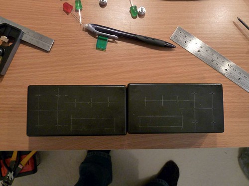
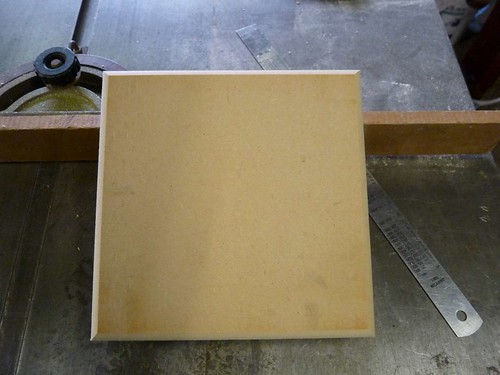
Instead, I got two pieces of 18mm thick MDF, and laminated them together.
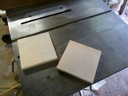
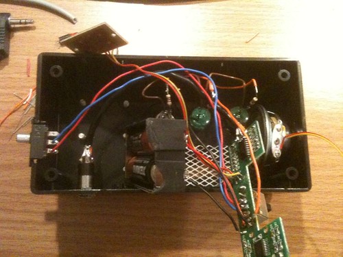
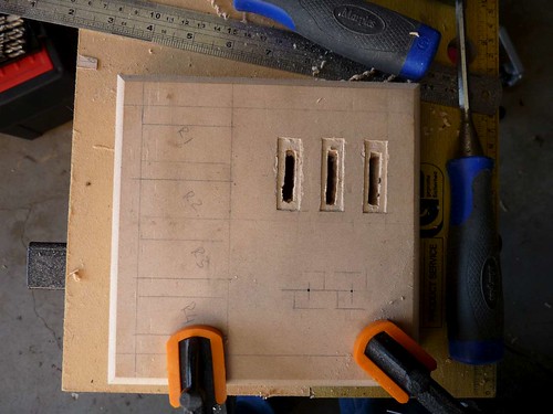
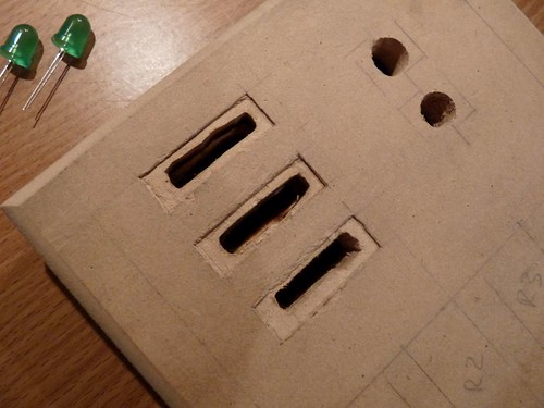
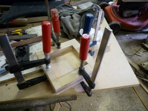
Before I laminated them together, I cut out the area where I will be putting the electronics, batteries, etc to light the box.
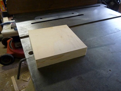
Once cut out, I glued the edge, clamped, and left to dry for 24 hours
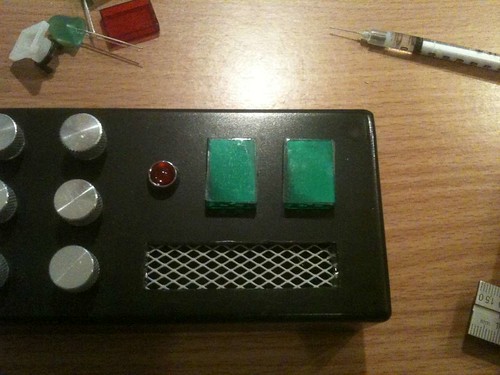
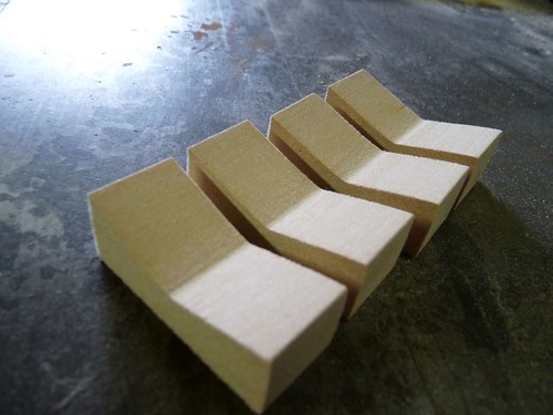
While that was drying, I set to work on the rocker "switches".
I used the guide from the STT to get the right height, angle, etc.
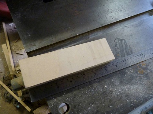
I ripped down a piece of MDF to be the same width as the switches are high.
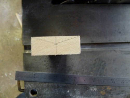
Then, marked on the end the angle (taking the highest point and the lowest, and then just drawing a line between). Please excuse blurry photo :\
I used the table saw, and adjusted the height of the blade, and moved the fence, so as to incrementally 'cut away' the wood. The only other way you could do this is with a router, and a custom jig - which I didn't really feel like stuffing around with
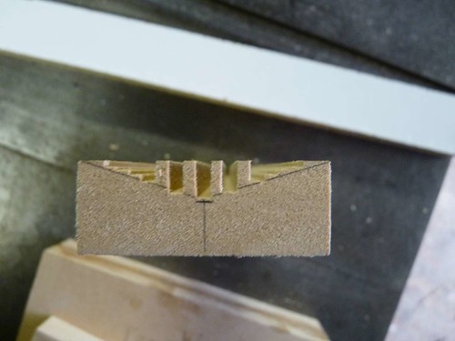
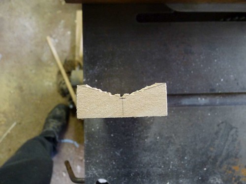
This left quite an uneven surface on both sides (due to the saw grooves). So, I just had to run some sandpaper over each side.
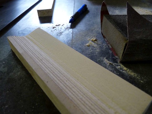
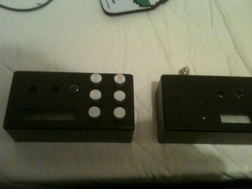
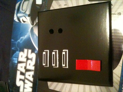
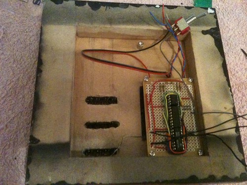
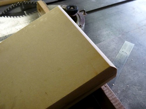
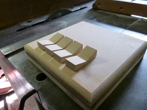
The following day I removed the chest box base from the clamps, sanded the edges, and then routed the top part with a bevel router bit.
I then cut out a number of rocker switches based on the width of the template.
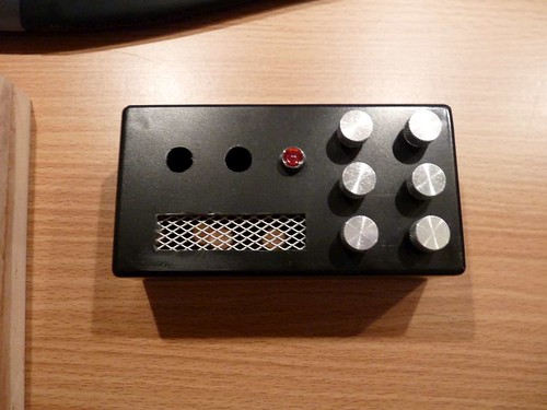
At this point I realised that they were probably a bit 'high' (ie. thicker than they should be). So, I used a band saw to cut them in half -- there was no way I was going to get my fingers the required distance to a rotating table saw. Once cut down they looked better proportioned with the chest box base.
Part 2: Belt Buckle [BB]
Whilst I was in the workshop, I decided to work on the belt buckle.
Using the template from the STT again, I cut out the main pieces from plywood
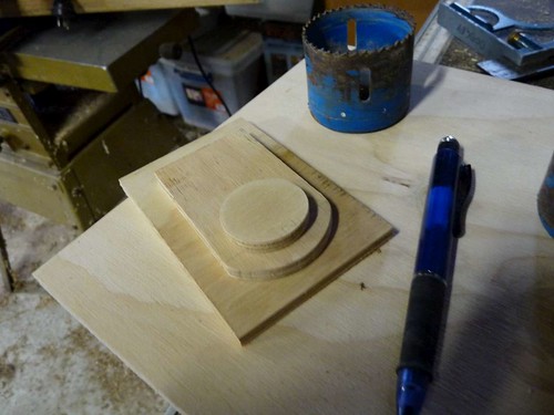
The back plate was simple: cut to size of template.
The middle 'curved' back was cut rectangular (as per template), marked a curve using a compass (you can use anything that's round and about the same height as the rectangle) and then I used a bandsaw to cut the curve out. You could also cut it out using a jigsaw.
The 'circle' I created by using a hole-saw to cut out (that big blue thing in the background of the picture - in case someone uses some other terminology )
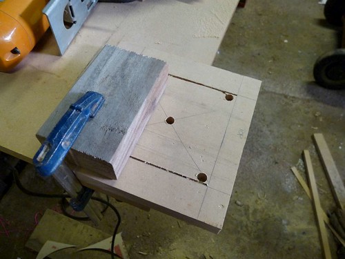
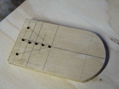
In order to get the 'grooves' into the middle, I first marked out where I they would need to go. Given that it's basically a triangular shape, I marked a triangle (this would provide the 'height' of each corresponding) and then the intervals at which they would occur.
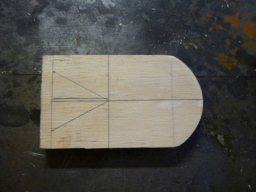
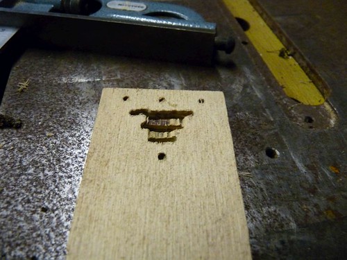
I first thought I would use a 3mm drill bit (which I think is 1/8th for those playing in Imperial land) to create a series of conjoining holes, that could then be sanded / filed out. But, this didn't go quite as planned.
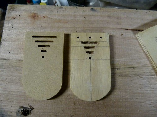
So I returned to my trusty router; having recreated the whole curved section of the buckle, I used a 3mm straight bit and created a little jig to help guide each interval based on its distance from the flat end.
This resulted in a much cleaner and consistant cut in comparison.
Final belt buckle

I started this build about a month ago in preparation for a costume party coming up. I've always wanted a Darth Vader costume since I was a kid, so I'm kind of thrilled to be part way there!
I started by purchasing a Rubies plastic helmet, and a 'full' costume (to take care of the cape and the rest) from here.
I used a lot of guides/reference material from the Sith Training Temple [STT].
I decided I would make the belt boxes and chest box with full lights to make it look more authentic (and a whole lot more awesome) -- as well as being a means of 'starting' on my way of creating a full costume.
NB:
This is most likely not going to be 'screen accurate'. I have a lot of respect and admiration for those who spend the time (and, where applicable, the money) to create detailed and accurate recreations of the Darth Vader costume. I just want a costume that will look good, and be recognised as being 'good enough'
Part 1: Chest Box [CB].
A lot of the guides / tutes I saw had chest boxes being moulded, or made from fibreglass. I've got more experience with wood, so I decided to make the CB from wood. Originally, I was going to do like darienvader did with his own chest box (http://www.therpf.com/f9/darth-vader-anh-chest-box-31710/#post436188) however, I decided I would avoid the hassle of routing out the back of the box.
Instead, I got two pieces of 18mm thick MDF, and laminated them together.
Before I laminated them together, I cut out the area where I will be putting the electronics, batteries, etc to light the box.
Once cut out, I glued the edge, clamped, and left to dry for 24 hours
While that was drying, I set to work on the rocker "switches".
I used the guide from the STT to get the right height, angle, etc.
I ripped down a piece of MDF to be the same width as the switches are high.
Then, marked on the end the angle (taking the highest point and the lowest, and then just drawing a line between). Please excuse blurry photo :\
I used the table saw, and adjusted the height of the blade, and moved the fence, so as to incrementally 'cut away' the wood. The only other way you could do this is with a router, and a custom jig - which I didn't really feel like stuffing around with
This left quite an uneven surface on both sides (due to the saw grooves). So, I just had to run some sandpaper over each side.
The following day I removed the chest box base from the clamps, sanded the edges, and then routed the top part with a bevel router bit.
I then cut out a number of rocker switches based on the width of the template.
At this point I realised that they were probably a bit 'high' (ie. thicker than they should be). So, I used a band saw to cut them in half -- there was no way I was going to get my fingers the required distance to a rotating table saw. Once cut down they looked better proportioned with the chest box base.
Part 2: Belt Buckle [BB]
Whilst I was in the workshop, I decided to work on the belt buckle.
Using the template from the STT again, I cut out the main pieces from plywood
The back plate was simple: cut to size of template.
The middle 'curved' back was cut rectangular (as per template), marked a curve using a compass (you can use anything that's round and about the same height as the rectangle) and then I used a bandsaw to cut the curve out. You could also cut it out using a jigsaw.
The 'circle' I created by using a hole-saw to cut out (that big blue thing in the background of the picture - in case someone uses some other terminology
)In order to get the 'grooves' into the middle, I first marked out where I they would need to go. Given that it's basically a triangular shape, I marked a triangle (this would provide the 'height' of each corresponding) and then the intervals at which they would occur.
I first thought I would use a 3mm drill bit (which I think is 1/8th for those playing in Imperial land) to create a series of conjoining holes, that could then be sanded / filed out. But, this didn't go quite as planned.
So I returned to my trusty router; having recreated the whole curved section of the buckle, I used a 3mm straight bit and created a little jig to help guide each interval based on its distance from the flat end.
This resulted in a much cleaner and consistant cut in comparison.
Final belt buckle
Last edited: