My BTTF Inspired Bag V2 Page 4

I really enjoy reading your progress. Mostly because it's way beyond what I'm capable of! :thumbsup

Thank you. I still learning this as I go.

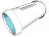
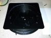
This is what the end caps should look like.

attachment.php

attachment.php
 

Attachments

  • Tube Bag Update 2.jpg
    Tube Bag Update 2.jpg
    71 KB · Views: 317
  • Tube Bag Update 3.jpg
    Tube Bag Update 3.jpg
    98 KB · Views: 299
Need feedback. I posted the question of Instragram and facebook, so posting here as well.

10 or 15 degree slope? The bag in the image above is based on 15 degrees.

attachment.php
 

Attachments

  • Tube Bag Update 5.jpg
    Tube Bag Update 5.jpg
    38.3 KB · Views: 294
Hello Cavx. Have you factored in the line going around the outside pieces? And on your current design those end pieces took a little too big. The handle is also not one long piece. It looks like the two half circles connect to rounded pieces of the main body that stick out.
f8bd9753-93d5-44a3-80ec-c4f06bb2eb1b.jpg

attachment.php
 
Last edited:
Here is a picture of it opened if you haven't see it. Here you can see a lip that each end of the handle connects to that goes down the length of the tube.
5cddda2b-7ad1-43bb-9a1b-d95d053c4583.jpg
 
I have seen this image (and 2 others) but not this big. Do you happen to have the other two in the same file size?

The lip can be added in after the two halves are cut apart.

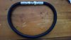
The bag is definitely fibreglass. You can see the chopped matting inside the handle.

The part that stumped people for a while is the grove around the ends. You can see here, it is a rubber U strip used to A help hold the lids but also to give the ends a nice finish. If they left the raw FG, it would have sharp parts.
 
The handle recesses may be fiberglass, but that is definitely plaster cloth inside the bag walls:

View attachment 677763

I've never seen the screen used prop in person, but I highly doubt it plaster. You can buy woven fibreglass matting instead of chopped matting. Most peoeple buy the chopped mat because either they don't know about the woven stuff or the place they purchased their glass from doesn't stock it (usually have to go to a dedicated fibre glass shop to buy it, not hardware stores). The idea is the same, except the finish is more uniform, and because the inside of the bag is a rectangle when laid out flat, makes sense to use woven mat. After a light sand, it would look the same.
 
I've never seen the screen used prop in person, but I highly doubt it plaster. You can buy woven fibreglass matting instead of chopped matting. Most peoeple buy the chopped mat because either they don't know about the woven stuff or the place they purchased their glass from doesn't stock it (usually have to go to a dedicated fibre glass shop to buy it, not hardware stores). The idea is the same, except the finish is more uniform, and because the inside of the bag is a rectangle when laid out flat, makes sense to use woven mat. After a light sand, it would look the same.

Sorry, but I disagree. I work with fiberglass, both mat and cloth, and what you're seeing in that bag is neither. The look, hole pattern, and texture is identical to plaster cloth. Google it, check out the pics, and I think you'll agree. If not, no worries.
 
Sorry, but I disagree. I work with fiberglass, both mat and cloth, and what you're seeing in that bag is neither. The look, hole pattern, and texture is identical to plaster cloth. Google it, check out the pics, and I think you'll agree. If not, no worries.

Not to argue, but what if these plaster wraps were used to layer up the outside of large diameter pipe? Would the pattern not transfer to the fibreglass? They made one bag and we don't really get to see the inside, so I would suggest that there was no need to make the inside pretty.

I have 2 sizes here - 10" (too small) and 12" (too large) and when I finally make vacuum formed pulls, I will use different thickness of rubber sheets to sleeve the inside of the 12" pipe to get the correct size for the lids, then use an other shim to make a slightly smaller part for the body.
 
Later today I made the call to screw and glue down this metal plate to eliminate at least one point of possible air leak. I had pre-drilled the holes the other day and today I used virtually a full tube of bathroom silicone to run a thick, wide bead right around the top of the plastic. I then placed the steel plate on top and screwed it down to compress the silicone down. After it has cured, I will counter sink the screws so that the plate is flat when the rubber gasket goes on.

attachment.php


I also bought 4 pairs of vice grips to act as quick release clamps to hold the top plate to the plastic. This top plate is needed because once a decent pull is made, the plastic will warp around the edges if not held in place and this warp will break the seal.
 

Attachments

  • 20161029_224534.jpg
    20161029_224534.jpg
    142.5 KB · Views: 486
I have picked up all the parts needed to make the tool for the body and lids.

I also decided to grab this guy today so I can do a vacuum seal test.

attachment.php


This is 1m long and fitted with 1/2 threaded ends. It is steel reinforced so it can not crush under vacuum. Cost me $114.00 at EnZed. Thanks for coming :)
 

Attachments

  • 20161102_110151.jpg
    20161102_110151.jpg
    77.5 KB · Views: 439
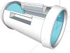
Hello Cavx. Have you revisited your 3D file to incorporate the details we discussed earlier?

Not yet. I need to get this whole thing up and running first so I can actually make vacuum pulls. Then fine details can be addressed after that.

The lip is used on the screen used prop due to the thinness of the fibre glass so it does not flex when picked up by the handles. I don't honestly know what the wall thickness I will end up with this yet. I am going to start tests with 4.5mm Perspex and see what we get. Ideally, 3mm walls would be strong but I may have to go upto 5 and even 6mm to get this.

There are two way to do this -

1. Traditional vacuum forming where the plastic covers the entire rig. There is a very tight time window for the plastic to be heated, pulled down and for all the air to be sucked out in order to make the process work. As a result, even pro vacuum form systems are prone to fail if the plastic is too thick.

2. Thermo forming where I use a silicone sheet as a membrane to complete the seal. This method requires the parts to be heated externally (I am in the process of modding the heater to work as an oven as well as top loading heat source) and are then placed in the tool whilst still hot. The membrane seals of the form and pulls the hot plastic into the shape of the tool to make the part. The real magic here is that the plastic is only thermally shaped, not stretched, so it does not lose any thickness. Also the parts are pre-cut to size and sometimes even shape meaning it more economic as it uses less plastic to do the same job.

I've been playing with vacuum forming for a few years now and I have done some good pulls and had a heap of fails.

So I have designed this rig to take the time/heat/seal fail factors out. The key reason I am using female tooling is that the seal can be made whilst the plastic is still cold.
This removes the need to rush to make a seal before the plastic begins to cool. This is why so many DIY vacuum forms fail.

Once the seal is made, the plastic can be heated from above. Traditionally, heated plastic forms a bulge towards the heater. If it touches, game over. In my case, this can not ever happen. Because a seal with suction has already been made when cold, as soon as the plastic is hot enough to be formed, suction pulls the plastic down away from the heater and into the tool.

I am using both a surge tank and vacuum pump, not a vacuum cleaner. I will therefore have greater than 6x the suction of a vacuum cleaner to evacuate the air and form the plastic. Unlike traditional vacuum forming, the heater in my system remains on during the process ensuring the plastic can not cool down whilst it is being formed.

Based on my tests at a smaller scale, if this works as I hope it will, I should be able to make parts from as thick as 10mm Perspex.
 
IT WORKS!

attachment.php


OK, the vacuum pump is attached to the vacuum degassing chamber which is then attached to the former chamber. The repressurisation valves allow suction to be isolated between the chambers. So what would happen is, the rig is set up as shown (paper removed of course), then suction is applied to get a seal. That 10mm (yes 10mm) perspex bowed in today. It was almost scary.

So once the plastic is under about 10"HG, the valve between the two chambers is closed off leaving the plastic bowed. The heater is then placed on top.
as soon as the plastic softens, it will be pulled down. By the time the plastic is hot, the degassing chamber would have been taken to a full 30"Hg ready to apply sudden surge of suction to the heated plastic. It will have no choice but to be pulled into the tool.

Next up is the heater assembly and then the rubber matting for thero-forming.

Exciting stuff.
 

Attachments

  • 14947643_10154687982123841_3062183097264318446_n.jpg
    14947643_10154687982123841_3062183097264318446_n.jpg
    130.6 KB · Views: 1,413
I believe the main body was paper tubing and the sliding opening panels were made of another material. You can see in this photo that there is the distinct angles line found in large paper tubes:

NikeBag.jpg
 
This thread is more than 5 years old.

Your message may be considered spam for the following reasons:

  1. This thread hasn't been active in some time. A new post in this thread might not contribute constructively to this discussion after so long.
If you wish to reply despite these issues, check the box below before replying.
Be aware that malicious compliance may result in more severe penalties.
Back
Top