ZF-1 BUILD UP problems and questions

photo35_zps406c0b6b.jpg

This is for the right side . Lift brackets go on the inside and as shown, invert for left side


photo40_zps1f98da5f.jpg
Order from inside to out screw , metal washer, lift bracket, metal washer , plastic washer, metal washer, plastic washer , whale plate , lock nut! Must be this way as it is calculated for measurements. Invert for left side

photo38_zpsd839a5e4.jpg

Upper shown left side here,
From outer side:
Screw lift bracket , plastic washer, sight bracket , lock nut
Invert for right side
photo36_zpsa14c87c8.jpg

Replace exactly as you have the original top plate with the new top plate and secure to side plates and whale plates
photo33_zps7b2b294a.jpg
Next smoothen up as much as possible under the front pod without compromising strength.
Make it as round as possible
photo32_zpsc94801f3.jpg
This next step takes time.
Carefully 1 mm at at time shave the alloy top plate to get an almost perfect fit to your pod.
On mine I left a lip but this should not matter if you
photo31_zps0af78fe5.jpg
These tabs were left originally to secure the shell , I have however cut off the rear for something else that I will show in the next couple of weeks.
In your case do not cut these yet
 
Last edited by a moderator:
photo30_zps31c1024d.jpg

Next present the rear plate for test fitting
photo29_zps3efe44c5.jpg

This may vary a little but I removed 15mm off the rear of the TOP plate as it is too long
photo28_zps2655e9a8.jpg

Rear plate goes underneath top plate
photo27_zps6972945b.jpg


Over lap the rear plate by 3mm past the rear upper strut block as shown and temporarily clamp the rear plate

photo26_zpsbc7d3fce.jpg

This took a little while to measure up but not hard.
I drilled and secured the rear plate to the top plate, if you are not sure ATM just leave it clamped
photo25_zps84a58bec.jpg

Make sure it is all straight
photo24_zps6a2494de.jpg

This was very difficult to work out when I did the laser and professional bending so this has to be adjusted a bit.
The cutting of the top plate will give you a very close guideline to where the rear plate last three holes should reach so bend this like the following
photo23_zpsd8a2316a.jpg

In relation to the whale plates
 
Last edited by a moderator:
photo22_zpsc04edadc.jpg

Back to the pod, clean as much of the rear as possible ,
photo21_zps53eddb85.jpg

Again as all pods will be different shave off the alloy whatever you need symmetrically so you get a very close fit
photo20_zpsdd600543.jpg
This angle may also have to be adjusted.
Now once the pod fits I would secure the rear plate to the top plate .
photo19_zps0b2f3297.jpg
Next screw the two rear shock mounts to rear plate
photo18_zps7a7758df.jpg
I removed a little material off the top of the rear shock mounts so they would not hit the pod
photo17_zps89c1a4d7.jpg


Lower support bar and rod goes between the last two holes , make sure the rear plate is secured and correctly fitted as shown prior to drilling these
photo41_zps6b6a3ef1.jpg
Glen was going to try and see what else we could do as this screw is not screen accurate but unfortunately it has to be here.
Now you can wait or do it this way like on mine.
I drilled and tapped either a 3 mm or a 4-40 cap head to hold the rear plate to the whale plates as there is no other form of attachment
photo15_zps35b68419.jpg
Cut and shape a piece of wood to fit inside the rear shock mounts, fibreglass or screw to pod and cover screws like I have
 
Last edited by a moderator:
photo14_zpsdda92d99.jpg

Time to check for these points
photo12_zps958e25c2.jpg

Position of pod

photo13_zps9ce2d29b.jpg

Position of pod
photo11_zpsefab3780.jpg


Pod sits very stable as there is minimum gap and the rear wood block although it will be bolted to the two upper holes found in the rear shock mounts, does not move at all ATM and its not attached

photo10_zps6e496bc1.jpg


think for this you are going to want it like mine.
Screw the rear eyelet that came in the screw bag to the rear shock part
Assemble as shown

photo9_zps12c434e5.jpg

Although superglue will hold these in place they will eventually pop, so tapping and putting a 4-40 grub to lock cylinder and piston head will be best
photo42_zps11d51f87.jpg
Naturally drilled on the bottom
photo7_zpsf77c263b.jpg

I put a washer and screw that slides easily inside the shock.
Then I bought the following US made springs , these work perfect
 
Last edited by a moderator:
photo6_zps81517ee3.jpg

So assembled should look something like this.
photo5_zps14ad2bab.jpg

We will assume that the sight is assembled
photo4_zpsb8130dfe.jpg

So assuming that the sight is assembled find the height and level the sight until it matches screen grabs .
Before drilling the shocker holes in the sight brackets make sure the shockers are fully extended and support the sight.
I did pullout and stretch the springs a little too prior to assembling.

Once the position of the sight is found drill the sight brackets and hook up the shockers
photo3_zps88956bdb.jpg

Now it's time to tweak and fit the sight into position .
At the start my sight closed too high
So I grind the whale plates a little so the shocker would lower
photo2_zps89ee1081.jpg

I removed about 5 mm of this curve so he shocker end would lower
 
Last edited by a moderator:
my god! i've got tonnes to do yet!

Thanks for uploading all of this Droidboy, and thanks Mars for taking the pics.

There is one huge task ahead of me!
 
Heavens above, seeing the breakdown like this makes me realize the insane amount of work that's gone into building this prop.

Truly humbling…

Highest regards

MARK
 
I think I'm going to go ahead and completely break mine down now that I have a pretty good feeling about how it all goes together and paint the frame black and sponge it. That way the second time I build it it's the final time.

Now to paint the pod.

Gregg
 
Gregg , to be honest i would build it all up and get everything right and then strip it down and paint it. Your going to stratch the paint no matter how hard you try not to. My plan is build it, strip it down, wet sand all the plates to get rid of scratches and then paint and reassemble.
 
To change things a bit , how's this?

I told a good friend about a possible plaque for this ZF.
He emailed back a kickass set of possible suiters!

I love them all but he has suggested only one that would work well due to the wording , these are to be machined out and will look 3D.
Either shapeways or CNC alluminium , still not sure

Regardless there is no doubt you would all agree that he has done an amazing job!!


zf2_zpsb2b28e59.png


zf4_zpsbdb7b146.png

zf3_zpsb28664cd.png


on this one and the first rendered one the gun is embossed or debossed!! I really dont know other than its the opposite to the rest!

zf_zps23f20cca.png
 
Last edited:
OMG! These are beautiful! But how to choose????

BTW, thank you Marcel and Droidboy, so much, for the latest pics and instructions. Time to get cracking again!
 
Its been a while....but hopefully someone can answer these questions please:

1. Shocks on gun barrel:

On the front end is there a nut on the inside of the barrel, or is the end of the shock just screwed into the ring and barrel?


2. Sight

Mars and Droidboy seem to have different order for the sight parts. Should the top metal bar of the sight be inside or outside?
When i received the parts this arm was outside (which means the countersunk hole is correct), where as Droidboys is inside. Which means the screw doesnt fit into the countersunk hole.

a2dcfc469674148.jpg


3. Rear sight shocks

What size screw and washer are used here? I think i have the right screw but the wont fit the washer. So thinking i might have the wrong washers on the frames!


Any help would be much appreciated guys!

Cheers
lewis
 
Sorry mate
Yes it's been a while
1: once the barrel and gun is assembled I would mark out where the rod is level after securing the barrel ring of course .
Mark out and drill the holes
You can either tap the hole with the correct tap and screw it right in or make a hole big enough so the rod goes through and attach the nut however this will be difficult to hold
So I would go with the first.
You would still need a bigger hole on the barrel as the bolt is longer than the barrel ring

2: ok this one I don't remember
Maybe kurtyboy can assist as his pod was shipped out last
I don't have mine assembled but the sight rod will give you the distance and work backwards

3:if you have lost the washers then any washer that can push and compress the spring will do
The washer is held by the screw and is wide enough to push the spring and small enough to travel inside the shocks
Hope this helps mate
Mars
 
Anyone got any pointers or ideas on the electronics "lens"?

Ive got this 1/4" acrylic I've sanded, doesn't look too bad.

Were you guys blacking it out at all? image.jpeg
 
i think this thread will be rekindled when these are ready....
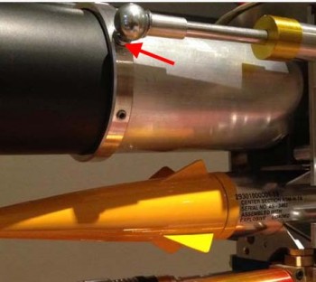
red tubes are getting anodized next tuesday , here is the setup

- - - Updated - - -

image.jpg

I have been trying to do these but it seems like such a waste as its hidden between the frame and plastic!!
maybe we should of done it outside everyones frame

IMG_6237.JPG
 
This thread is more than 6 years old.

Your message may be considered spam for the following reasons:

  1. This thread hasn't been active in some time. A new post in this thread might not contribute constructively to this discussion after so long.
If you wish to reply despite these issues, check the box below before replying.
Be aware that malicious compliance may result in more severe penalties.
Back
Top