You are using an out of date browser. It may not display this or other websites correctly.
You should upgrade or use an alternative browser.
You should upgrade or use an alternative browser.
Blade Runner Snub Nose Blaster Project
- Thread starter DaveG
- Start date
I have a Rick Ross snub kit available if anyone is actively looking.
Payment sent!
Woo hoo! I got me a Rick Ross Snub Nose! Now I don't need to finish this one.
")
MrSinistar
Well-Known Member
Kidding! :lol
Phew! Glad you were joking! XD
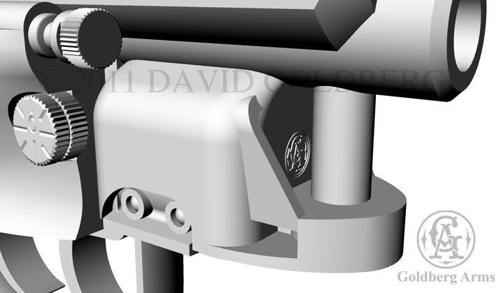
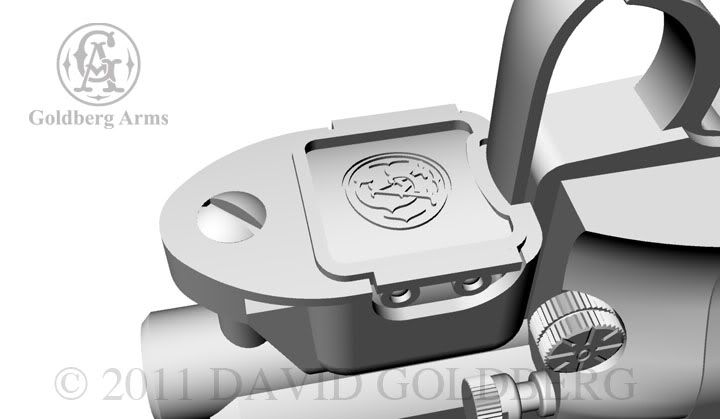
Here are further refinements to the ammo clip housing. Added the recesses and LEDs and the embossed Goldberg Arms logo. These parts will be 3D printed. A note about the slotted screwhead on the bottom. One of the things that has always bothered me a little about the hero prop was the use of hex head cap screws instead of slotted fillister head screws, which are normally used on firearms. So on my version, fillisters will be used.
Back to Work
I'm on hiatus from the movie for a couple of weeks so it's back to work on the Snubby! Here are the, almost finished, side covers. They were milled out using the computer model on the CNC router and then, in the case of the right side cover, further refined with chisels, files and sandpaper.
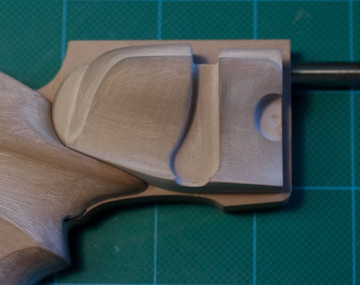
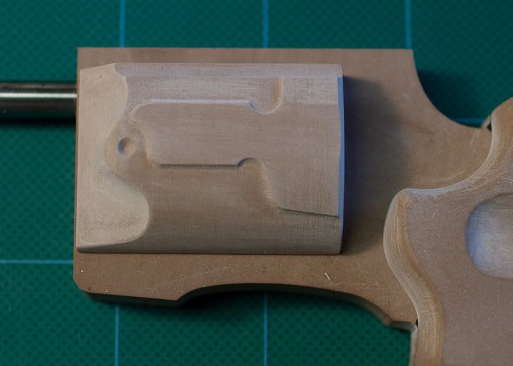
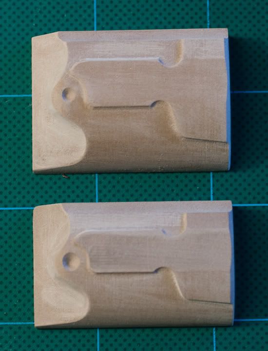
One of the great things about working with the CNC is the ease of editing the shapes. Once I milled out the left side cover I felt it was too small when placed on the frame. So I scaled the computer model, but in only two directions, height and depth, and milled out a second, more satisfactory part. Here's a photo of the two versions, the first one on the bottom, and the final part on the top.
I'm on hiatus from the movie for a couple of weeks so it's back to work on the Snubby! Here are the, almost finished, side covers. They were milled out using the computer model on the CNC router and then, in the case of the right side cover, further refined with chisels, files and sandpaper.
One of the great things about working with the CNC is the ease of editing the shapes. Once I milled out the left side cover I felt it was too small when placed on the frame. So I scaled the computer model, but in only two directions, height and depth, and milled out a second, more satisfactory part. Here's a photo of the two versions, the first one on the bottom, and the final part on the top.
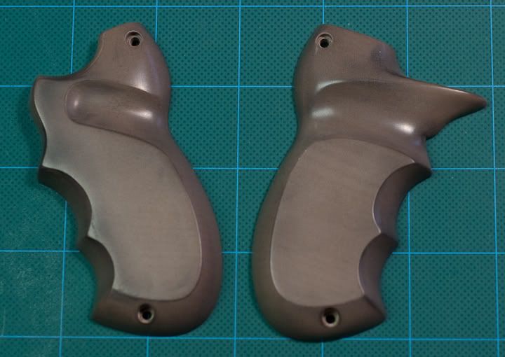
Here the master grip patterns have been finished up. The surface was progressively wet sanded with wet-n-dry sandpaper (the black kind) starting with 280 grit, then proceeding through 320, 400, 600, 1000, 1500 & 2000 grits. Then they were polished to a soft shine using a buffing wheel and White Diamond Tripoli compound.
Rather than cut the checkering patterned into these patterns, I'm going to pull molds and then cast up intermediate "blanks". This will allow me to experiment with different checkering patterns and inlay options.
Rather than cut the checkering patterned into these patterns, I'm going to pull molds and then cast up intermediate "blanks". This will allow me to experiment with different checkering patterns and inlay options.
so I love seeing you using Rhino and the CNC router, but I'm wondering why you didn't at least router out the actual design in two halves and then go in and fine tune it by hand, or have it completely 3D printed??? It would have cost like $500 tops! What the heck?? It looks great don't get me wrong but I feel like you're working backward?
FYI, I had a lot of success with laser cutting a cross hatch pattern on these guns:
http://www.techmagicdesign.com/blasterPistol.html
I CNC'd the wooden handles out and finished them by hand, then I created the vector lines for the grid, using the profile line to the handles. I put a piece of acrylic into the laser cutter, cut the profile line, and removed the piece. I put the wooden grip in it's place, and then ran the grid lines, they were located perfectly that way. Scaling is obviously important but not difficult.
You can also export .step from Rhino and open in Solidworks/Inventor if you wanna get crazy with the mech. design or generate working drawings in a snap. I totally understand making pieces by hand if you're working from drawings and doing it for the fun of doing it that way, just seems odd to draw the line beyond using 3D software and CNC, but before using it to it's fullest potential.
Last edited:
Chaz,
Not really working backwards. It's a matter of time and detail. The grips are actually very complex shapes. It would have taken me far longer to model them in the computer than it did to sculpt them by hand. Plus the "feel" of the grip was very important and being able to hold it while developing the shape was essential. Since the finished patterns need to have a gloss surface in order to yield clear castings, the progressive wet sanding by hand would have been required even if they had been completely formed with the CNC.
Likewise with the two side covers. The left side cover was completely modeled and milled on the CNC, needing only a little sanding to cleanup the cutting steps. But the right side cover, like the grips, is a very complex shape. So I modeled the basic form, cut that with the CNC and then hand sculpted the finer detailed curves. Again, it took far less time to sculpt by hand then to model in the computer.
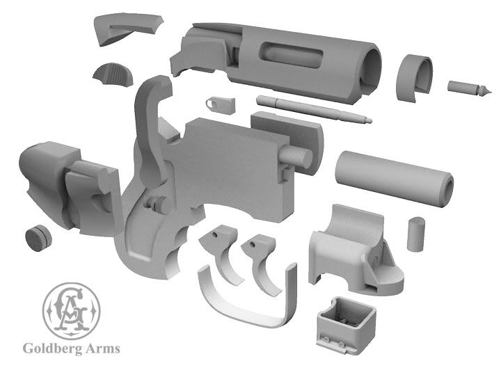
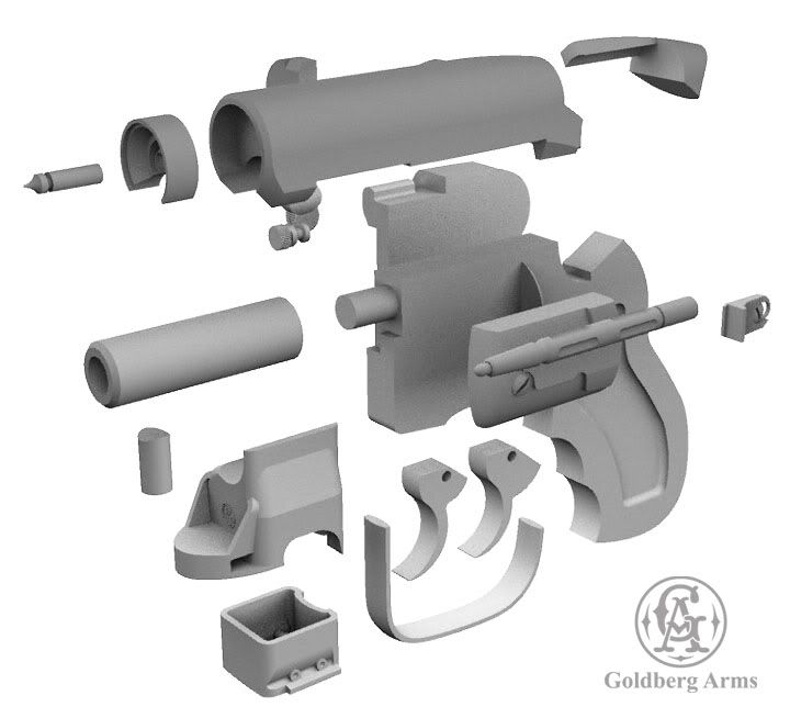
As to just CNCing or 3D printing the whole blaster in two halves, the level of detail required and the desired castings make this impractical. This is going to be a pretty high end kit when done, and require some work to put together. Not just one of those $40 one piece castings you find on Ebay! Separate parts are also advantageous for painting and finishing, allowing different parts to be painted different colors or metal finishes, if desired and then assembled.
Several of the parts like the receiver, clip housing, bolt lever and thumb slides are being 3D printed. I should have the first batch of those parts back by the end of the week.
Not really working backwards. It's a matter of time and detail. The grips are actually very complex shapes. It would have taken me far longer to model them in the computer than it did to sculpt them by hand. Plus the "feel" of the grip was very important and being able to hold it while developing the shape was essential. Since the finished patterns need to have a gloss surface in order to yield clear castings, the progressive wet sanding by hand would have been required even if they had been completely formed with the CNC.
Likewise with the two side covers. The left side cover was completely modeled and milled on the CNC, needing only a little sanding to cleanup the cutting steps. But the right side cover, like the grips, is a very complex shape. So I modeled the basic form, cut that with the CNC and then hand sculpted the finer detailed curves. Again, it took far less time to sculpt by hand then to model in the computer.
As to just CNCing or 3D printing the whole blaster in two halves, the level of detail required and the desired castings make this impractical. This is going to be a pretty high end kit when done, and require some work to put together. Not just one of those $40 one piece castings you find on Ebay! Separate parts are also advantageous for painting and finishing, allowing different parts to be painted different colors or metal finishes, if desired and then assembled.
Several of the parts like the receiver, clip housing, bolt lever and thumb slides are being 3D printed. I should have the first batch of those parts back by the end of the week.
Similar threads
- Replies
- 18
- Views
- 1,097
- Replies
- 2
- Views
- 659
- Replies
- 1
- Views
- 919