Iron man motorised faceplate electronics tutorial!!!

DONT connect those eye led panels DIRECTLY to your Arduino..

you are gonna blow it!! (the Arduino..not the leds)

you are trying to pull more current than the pin can safely give!!!!!

it cant be any more clear than the two diagrams myself and memebr posted.. :)

and unless your LEDS are rated for around 2.1-2.2 vF.. then its incorrect ;)


Did you try to meter by using JUST the blink (put a LONG delay in there).. and see what the meter says?

No i havent tried that. But does it really matter now? As you said: i should not power it directly from the arduino or i will blow it.
So i need to connect them using a transistor functioning as a switch.
I'll continue tomorrow. Over here its bedtime right now.

Ps. I tried to draw a scematic using frizzing. Damn more difficult then it looks.
 
Any reason you went with those? Just curious as I'm trying to decide specifically which ones I need to buy. I am looking at the Hitec HS-56HB servos which appear to be slightly smaller and slightly faster, but less torque to them.

A local hardware store advised me these. Very small. Strong. Fast. I am a noob to so i took advice from an expert
 
I got some generic 'white' ones from HobbyKing.. just for because! (to play with)

was ordering other stuff.. threw them in cart..

when I got to the IronMan helmet portion.. if they dont work.. (for me) its a simple swap for some higher torque/metal geared ones..etc..


I need to calibrate mine and work out the correct range of movetment..etc..


JayCVenlo -

why? to ensure your board is working properly..and not blown I guess..

you were trying to pull tos of current through one pin..now you say you only get +2.8v out of a pin?

thats why I guess.. :)
 
Last edited by a moderator:
I got some generic 'white' ones from HobbyKing.. just for because! (to play with)

was ordering other stuff.. threw them in cart..

when I got to the IronMan helmet portion.. if they dont work.. (for me) its a simple swap for some higher torque/metal geared ones..etc..


I need to calibrate mine and work out the correct range of movetment..etc..


@JayCVenlo -

why? to ensure your board is working properly..and not blown I guess..

you were trying to pull tos of current through one pin..now you say you only get +2.8v out of a pin?

thats why I guess.. :)

I will see if i can buy a transistor tomorrow and see if i can get it to work. Because that will be my second to last thing i need wired.
What i also want is to make a switch between the battery pack and arduin vin port. Basically my primary on and off switch for the helmets power.
 
Last edited by a moderator:
msleeper
I'm using those generic 15kg servos, TowerPro MG995D (metal gear digital servos)


xl97
His Arduino board could be the 3V model... if the thing was damaged it would stop working


JayCVenlo
Maybe you have a 3V arduino in your hands, so the best thing to do is use transistors to toggle the leds, this way the battery pack will provide the power to the leds, and the arduino will just control it.
 
Last edited by a moderator:
@msleeper
I'm using those generic 15kg servos, TowerPro MG995D (metal gear digital servos)


@xl97
His Arduino board could be the 3V model... if the thing was damaged it would stop working


@JayCVenlo
Maybe you have a 3V arduino in your hands, so the best thing to do is use transistors to toggle the leds, this way the battery pack will provide the power to the leds, and the arduino will just control it.

Membre,
Yes that is exactly what i want to do! :D

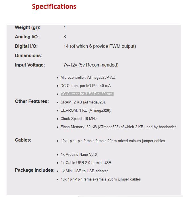
This is the arduino i ordered. Arduino NANO v3.0 ATmega328P + FREE USB CABLE + jumper cables | eBay
 
Last edited by a moderator:
As i was suspecting, you have in your hands a 3.3V Arduino nano. under stress the pin would have a considered Vdrop, as you can see. you have to use transistors if you wanna link 5V to your leds.

nano_zps5ad6ee5d.jpg
 
the transistor "I" use is an SMD version.. (you dont want that.. but a through hole variant most likely) :)


Also.. with you having a +3.3v based board.. your meter readings make much more sense...(accurate).. then having the more common +5v based Arduino board..
 
Any reason you went with those? Just curious as I'm trying to decide specifically which ones I need to buy. I am looking at the Hitec HS-56HB servos which appear to be slightly smaller and slightly faster, but less torque to them.

I am using the Hitec HS-56HB as well. I have tried multiple servos, and I really like these. They are small, fast and do the job. They also have metal/composite gears. The torque is slightly less than some of the others but work fine on all my "cast" helmets. Havent tried them on any of my heavier fiberglassed/bondoed helmets but I dont think it would be a problem.
 
the transistor "I" use is an SMD version.. (you dont want that.. but a through hole variant most likely) :)


Also.. with you having a +3.3v based board.. your meter readings make much more sense...(accurate).. then having the more common +5v based Arduino board..

XL,

i bought a npn BC547B transistor. Connected it the same as in your schematic, but the light were not bright at all. There was enough power going in. i dont understand.
Then i directly connected the postive and negative cable to my (5v)positive and negative rail on the breadboard. The light were bright as the should be.
But then i noticed the VREG was getting really hot?

What am i doing wrong?????
 
1.) link to your transistor of choice? (as stated not all transistor have the same PINOUT)

2.) did you look at the datasheet for it? or just 'guess'?

vreg hot? what is your battery pack again? +7.4v? (shouldnt be too hot)
 
1.) link to your transistor of choice? (as stated not all transistor have the same PINOUT)

2.) did you look at the datasheet for it? or just 'guess'?

vreg hot? what is your battery pack again? +7.4v? (shouldnt be too hot)

1. It should be like in this datasheet http://www.produktinfo.conrad.com/datenblaetter/150000-174999/155785-da-01-en-TRANSISTOR_BC547B_TO92.pdf

2. it says its the pinouts are the same as 546/547/548

Yes battery pack is 7.4V regulated to 5V. connected the leds directly to the 5V rail.
 
ok i followed this guide down to a T and all i get is some vibrating servos. No light and no response to the button press. What am i doing wrong? I tried it with a arduino micro and thought that had something to do with it so I then tried it with my uno and i get the same effect. need help
 
Ok I figured it out. I don't know if someone hit on this yet but the switch was positioned wrong according to the tutorial. Maybe it's just me but now it all works.
 
Ok I figured it out. I don't know if someone hit on this yet but the switch was positioned wrong according to the tutorial. Maybe it's just me but now it all works.

I dont believe the switch is wrong in the tutorial. Maybe you just connected it wrong the first time. Happend to me also. You think you've got it right - doesnt work - you double check - you notice you made a mistake. Happens to everyone. ;)

good luck with the rest. The first setup is the easy part. :p
 
Wow this thread keeps growing and growing! Full of great info xl97 that custom board is cool, I wanted to do something like that but well I have a very light grasp on all this stuff and developing SMD PCB boards a lil out of my ball park right now. I have taken a little while and started back up on my helm, but I burnt out my Accelerometer by sending it 5V instead of the 3v it needed. So now I play the waiting game again. But here is a little update of my progress, don't mind the wires all taped up they are temp until I get everything in there fitting right.

http://www.facebook.com/photo.php?v=10201372826066894
 
This thread is more than 4 years old.

Your message may be considered spam for the following reasons:

  1. This thread hasn't been active in some time. A new post in this thread might not contribute constructively to this discussion after so long.
If you wish to reply despite these issues, check the box below before replying.
Be aware that malicious compliance may result in more severe penalties.
Back
Top