@JayCVenlo -
you cold probably just connect your 'bar' (or whatever) to an Arduino pin..and whenever you close connection (not sure if its hi or low its looking for)
it should trigger the sound.....no?
as for the leds.. it was already discussed (in length) that you can NOT drive multiple leds from an Arduino pin..
you need to us a resistor to 'trigger' this....
what is your led strip rated for? how many leds? in what configuration?
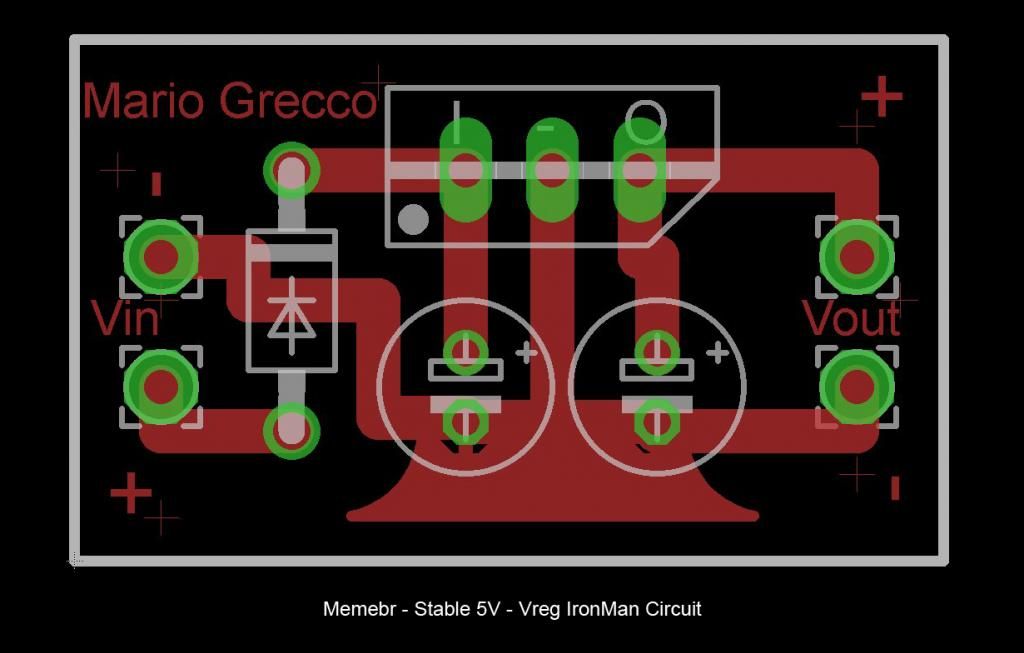
make sure your regulate the power before the transistor/leds.. transistor is more or less just a trigger, that lets the voltage/current flow through it to the target device/component(s)..
1. Yes the bar is the switch. As soon as it hits the metal underneath it, the chip activates and plays the sound sample. What you are saying is connect the bar to a arduino port, and connect the metal underneath to ground.?
2. What should the code look like?
3 the 2 led strips are 12v with each 6 leds. I believe per 3 leds there is a build in resistor. When i just connect them to a 9 volt the run just fine. But how do i connect them to the arduino for fading and flickering?
Any advise on the gp battery pack?
It was okay at first but now with the external control push switch the servos automaticcaly go down after going up, without me pressing. With the test button on the breadboard i didnt had this problem.[/QUOTE]
if you read the thread.. MOST of the talk has been about the following:
1.) powering your servo(s) from an external battery pack (NOT THE ARDUINO)
** you are powering the servo from the Arduino

2.) connecting the GNDs from the battery >> arduino ..... battery >> servo ...... GND Arduino >>> GND Servo
** you have GND from Arduino to servo
3.) you can NOT power more than 1 led off an Arduino pin.. to control more.. use a transistor (or equivalent) (as posted in many of the wiring diagrams here)
**you are powering your led array from the Arduino.
think of it like this:
your battery source needs to power/connect to:
* arduino
* servo(s)
* transistor (for leds)
*you'll need to connect/add a wire from a GND pin on the Arduino to the servo(s) as.. (same place where the GND wire from the battery pack is going to the servo)
as far as your battery pack.... not sure hwo that works to be honest... although Im sure it easy to look up.
when powering through the USB.. Im not sure what/how they exactly works and if it varies for each model..
you might be able to use either the VIN or RAW pins? to tap the 5v USb battery thing directly? again Im not sure, this isnt the approach I would have used.