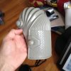
Mark 46 build 3D print

Been playing with the electronics and was wondering if any the technical adruino experts can help me out with the sketch.

I have a Adruino Pro Mini that is running 2 neopixel rings and 10 additional RGB LEDs from pin 6. The first 26 LEDs are dedicated for the Arch reactor and then followed by 10 RGB Leds that are spread out through out the chest. back and arms. I would like to get the first 26 LEDs in the arch reactor to power up (Typical reactor style) and then followed by the other 10 powering up gradually (simultaneously) after that.

Any assistance would be greatly appreciated.
 
I'm very much interested in seeing both hinge designs. I'll need one too, but it's a bit overkill if I start making one too :)
 
I have a Adruino Pro Mini that is running 2 neopixel rings and 10 additional RGB LEDs from pin 6. The first 26 LEDs are dedicated for the Arch reactor and then followed by 10 RGB Leds that are spread out through out the chest. back and arms. I would like to get the first 26 LEDs in the arch reactor to power up (Typical reactor style) and then followed by the other 10 powering up gradually (simultaneously) after that.

That's a pure software question. For something roughly similar I did, I wrote a bytecode engine that could change LED brightness, pause and run loops (counted or infinite). I plan on using the same system with NeoPixels. What you want can be done with pure C, but the timing logic becomes more complicated to write and maintain compared to the bytecode approach. If the lights are supposed to be independent, then it makes sense to run two or more bytecode machines in parallel, which is also pretty easy to do.

The bytecode instructions are written using C preprocessor macros that generate arrays with the instruction codes. The bytecode engine fetches and executes instructions from the array until it runs into a pause instruction. It's very much like emulating a very simple microprocessor and writing assembly language code for it.

I have some documentation & source code in my blog, but I'm hesitant to recommend it, because the code is not directly applicable to your hardware. You would have to be pretty good at C programming to take my code and modify it to control NeoPixels. If you are good at C programming (or have someone who is good at it), then writing your own code based on the ideas above isn't all that hard. I wrote all my code in a couple of evenings (and it was my first Arduino coding project). However, I have a strong software background and plenty of previous C/C++ experience.
 
I'm not sure if anyone have came across a hinge set up for the MK46 helmet just yet but I found this on the internet, figured it would maybe help give someone ideas for the mechanics on the MK46 helmet. Sorry these were the best images I could find, terrible quality!

Thanks for sharing this. This is exactly what I wanted to create. If anyone could recreate these parts and share with the community it would be Awesome. Could you share the actual link mabie we could try and contact the originator.


If your looking for a hinge set up for the 46, you should try https://www.shapeways.com/designer/therealstark/creations. There are couple of hinge designs you can download but if you want the servo 3.0 setup, you'll have to contact him directly. He's a pretty awesome dude and I used the wide hinge design on my mark 3 and it worked out great.
 
Been playing with the electronics and was wondering if any the technical adruino experts can help me out with the sketch.

I have a Adruino Pro Mini that is running 2 neopixel rings and 10 additional RGB LEDs from pin 6. The first 26 LEDs are dedicated for the Arch reactor and then followed by 10 RGB Leds that are spread out through out the chest. back and arms. I would like to get the first 26 LEDs in the arch reactor to power up (Typical reactor style) and then followed by the other 10 powering up gradually (simultaneously) after that.

Any assistance would be greatly appreciated.


show pics of how you have things wired up...


I dont think having 10 RBG's on a single pin is going to work... (a mentioned a single Arduino pin can only deliver roughly 20mA (some say up to 40mA) of current.. that enough to light up ONE accent led (single color).. an RGB led at full brightness (all colors) will pull around 60mA.. EACH!!!.. I'm not even sure/clear HOW you can connect 10 RGB leds to only 1 pin anyways...


are you saying these are 'neopixels'? and not really just an RGB led?

(only way I can see this making any sense)

Have you walked through the Neopixel tutorials at Adafruit? I would start there...

These are the neopixel rings. They have red, blue and green. I've figured out how to adjust the brightness and colors so far. I'm just going to add 10 more of the wearable neopixel RGB's liked via the output of the smaller center ring.

18DEFF06-D974-487C-B041-AF90DB52F419_zpsszk9cwjw.jpg


FA2957A7-D687-4701-B7A9-9CE0FE163556_zpspb9eb7bb.jpg
 
ah.. ok..

so these '10' RGB LEDS.. are really RGB leds.. but Neopixel LEDs.. (there is a HUGE difference)

RGB leds are (more or less) 3 separate leds (dies) under the same dome... (separate resistors....and current needs..etc)

a Neopixel (RGB) led has a built in chip to control it.... (and the whole thing runs of 5volts)...


That being said.. you might want to use a different pin for the other Neopixels..


So you want the Arc reactor neopixels to fade in...

-then- the remaining Neopixels to 'fade-in' all at once (gradually)


is this the case/correct? That should be fairly easy to accomplish!


I would also go back and add the cap and possibly resistor like outlined in the Adafruit tutorials.. so you dont ened up ruining anything or blowing the first leds in your Neopixel rings.
 
devildog12, Ya Ryan is really cool he has helped me out with a lot in the past, I bought one of his unibeams for my Mark42 but never finished that suit now the unibeam just sits on my desk. I didn't think of getting ahold of him. Thanks for the comment!
 
Last edited by a moderator:
Thanks Devildog. I've looked at his builds before. Totally Awesome! I really like his voice activated version for the helmet. I would hope to get to the point I actually design something like that myself.

I looked at his hinges, but can you download his designs?
 
Thanks x197, I was running to the store today to pick a few resistors up. I have a sketch also I want to share with everone that I got from the Stan Winston School of Arts tutorial involving a digital button switch. It's very close to what I was looking for and I think I might have this close to being figured out. Just need to tweak the sequence and the colors. He was actually using around a 50 LED neopixe strip for his project. Will share the sketch I have shortly for other Mark 46 builders if they are interested.
 
Thanks Devildog. I've looked at his builds before. Totally Awesome! I really like his voice activated version for the helmet. I would hope to get to the point I actually design something like that myself.

I looked at his hinges, but can you download his designs?

I've actually done the voice activated helmet and it's really fun however very hard to do. I hope to integrate the voice controls into my Mark 45 suit. Yeah you can download this normal servo and wide servo hinge from Shapeways. His servo 3.0 you'll have to email him for it.
 
Last edited:

I have a degree in computer programming so setting it up wasn't a big deal. However it was a monster to finish up and I got it nearly complete and then I had to move and the helmet got crushed during the move :(
 
Last edited by a moderator:
could you share what you did with your eyes for your faceplate? looks super clean but I can't tell how do you see through it? The hinge essembly you guys are working on is exactly the type i'm trying to do as well and integrate it directly within the helmet. Hopefully you guys share the hinge design when finished
 
Just finished the mother mold and first raw cast of the face shield for the helmet. Will probably do a limited run on the helmet when I am finished.I have to admit It didn't come out to bad for my first time doing a mold. Will just need to make it a little thicker on the final run.


5998961D-E35D-49B6-9242-9355568CA932_zpsjkufhu4h.jpg
 
Quick update on the hinge...IMG_3417.JPGIMG_3418.JPGIMG_3415.JPGIMG_3442.JPGIMG_3443.JPG

I remounted the servo arms half way up the arm, which provides enough clearance to open and not lift the face plate as high. My makeshift servo mount is a tad wide, but I needed the width to clear the top beak part of the helmet. Gobs of hot glue and masking tape for the fit up. Also, I found these soft knee pads at Harbor Freight, figured they would make a decent shoulder filler piece! For $5, i can't argue. I'll dress them up a bit more and see about attaching them properly. Just wanted to give anyone state side a heads up!
 
This thread is more than 4 years old.

Your message may be considered spam for the following reasons:

  1. This thread hasn't been active in some time. A new post in this thread might not contribute constructively to this discussion after so long.
If you wish to reply despite these issues, check the box below before replying.
Be aware that malicious compliance may result in more severe penalties.
Back
Top