You are using an out of date browser. It may not display this or other websites correctly.
You should upgrade or use an alternative browser.
You should upgrade or use an alternative browser.
Bay 327 need wall info
- Thread starter MARK M3
- Start date


scifiguy67
Active Member
Just looking at the craftsmanship on the falcon & docking bay set makes me miss the days when they used models... nowadays they just hit the button on a computer & it's done.
Just looking at the craftsmanship on the falcon & docking bay set makes me miss the days when they used models... nowadays they just hit the button on a computer & it's done.
I do CGI for a living and I can assure you it is no where near as easy as that.
Darth Humorous
Well-Known Member
Hmm… attachments say invalid attachments.View attachment 816443View attachment 816442View attachment 816441View attachment 816444
A few more of varying quality...
Cheers,
K>
Mark
portland182
Well-Known Member
Britcinescribe
Well-Known Member
I’m in the process of making the exact same diorama. You have a difficult task ahead of you. Are you just making the light area around the docking bay maw, or the actual bay interior?
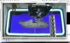
Jason Eaton has made a marvellous model of the large squarish gantry hanging to the left...you should check his page for reference. In the middle of the bay, ILM made a miniature of their Dykstraflex camera, which is hanging upside down. That was removed for the Special Edition (pointless change).
The area around the bay entrance on left and right is simply repeated panels of the standard live action wall “Death Star Air Supply System”, but scaled down.
There’s a massive problem with the left side of the bay (as you’re looking out into space), as (very visible at the rear of the live action set) are two cylindrical piston-like mechanisms (which I think are painted flats). This mechanism is exactly at the rear edge of the bay, and is not visible on the ILM miniature when the ILM Falcon is entering the miniature. My in-universe continuity rationale fix for that is that the panel section of the wall either raises or lowers after the Falcon is at rest to reveal that mechanism.
The exterior matte painting of the space troopers with the turbolasers changed the docking bay ever so slightly for the Special Edition.
ALL versions of the docking bay (original and SE) in the film don’t make sense. Peter Ellenshaw made an error painting the bay matte painting in the original film. There is a forced perspective effect created by using ingenious wallhangings, and painted chevrons on the floor of the bay. This effect is only really visible from one spot within the set (spot just below the front right mandible of the Falcon… Ironically, an angle that doesn’t seem to be used within the film.) The closest shot in the film giving this visual illusion effect is the standard “continuity publicity photograph“ of all of the storm troopers standing in rows when Darth Vader enters. ( you could see that the painted flat off the wall on the left hand side of the bay, and very thinly painted Chevron lines behind the Falcon, from that angle extend out in the proper perspective to the regular chevrons painted alongside the lift area by the Falcon). The down angles on the Falcon are painted incorrectly: the entrance maw isn’t extended out to the left to correct the force perspective, neither is the length of the bay similarly altered in order to correctly match the forced perspective trick. Stinson Lenz (who I believe is on here… Hi, Stinson!) and I were discussing this some weeks ago, and Stinson made a subsequent terrific CG representation of what the corrected Death Star Bay would look like.
https://deeplyobsessed.blogspot.com/2018/02/actual-depth-of-docking-bay-327.html
Compounding this fact, are that the CG artists who did the special edition shot completely screwed up the bay. Not only did the dimensions of the lit maw change from shot to shot, but they added in the Death Star 2 docking bay structures from ROTJ, which are totally wrong; and they also made a total balls-up of the left side of the frame (screwed up the wall with a ridiculous digital set "enhancement", and buggered up the catwalk gantry so that it now makes no continuity sense.)
Last edited:
Britcinescribe
Well-Known Member
Britcinescribe
Well-Known Member


- - - Updated - - -


Britcinescribe
Well-Known Member


Britcinescribe
Well-Known Member
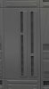
For the entrance maw, the central "vents" seen in the panel at centre of frame here, are what you want. The simplest solution would be to create a template, paste it to a graphics program, and multiply repeat it until you have your wall, then print that out (a sheet of self-adhesive photographic paper or a decal maybe). But for the scale of your Falcon, you need something tangible. It'd be cool to 3-D print it, but likely expensive. So, either you're going to have to construct them all individually (lots of cutting until the wee hours/molding), or maybe see if you can find somebody who can laser-cut the vent pieces in bulk and then glue them in place.
Attachments
Britcinescribe
Well-Known Member
There's actually some contention, here. On the photographs of the Elstree set, while the deck level panels have the grilles within them, the upper wall repeated vent panels *seem* as if they don't. There's no real close-up pictures of them to corroborate this. It's very possible the Elstree carpenters left off the grilles on the panels to save on expense (that was a pretty big wall, after all.) It's impossible to see from any of these ILM photographs what they did with the panels. So, there's a question: do you replicate the "cost saving set", or do you go for in-Universe accuracy, and put the grilles in that didn't exist, there?
Last edited:
Keiko
Sr Member
Hmm… attachments say invalid attachments.
Mark
Fixed, I think.
K.
Britcinescribe
Well-Known Member
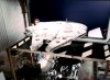
Looking at the one shot of the ILM chap wiring in the gantry crane, that's about the best shot of the vent panels on the wall. They look really peculiar. In a few of the panels, there seems to be a "three dimensional" effect to the panels, illustrating that they were cut-out. Yet for the grilles in the panels (which do seem to be there), there's a repeated uniformity to the defects in the panel grilles, which leads me to suspect they might be something as simple as a grille that was drawn, and then photocopied onto paper and the strips cut and glued into place.
Darth Humorous
Well-Known Member
Fixed, I think.
K.
Yes they are. Looks great. Thanks!
Mark
- - - Updated - - -
Argh, sorry, Here's the repeated vent pattern.
There's actually some contention, here. On the photographs of the Elstree set, while the deck level panels have the grilles within them, the upper wall repeated vent panels *seem* as if they don't. There's no real close-up pictures of them to corroborate this. It's very possible the Elstree carpenters left off the grilles on the panels to save on expense (that was a pretty big wall, after all.) It's impossible to see from any of these ILM photographs what they did with the panels. So, there's a question: do you replicate the "cost saving set", or do you go for in-Universe accuracy, and put the grilles in that didn't exist, there?
View attachment 816519
Another invalid attachment. Must be contagious.
Mark

Britcinescribe
Well-Known Member
Oh, wow! Thank you thank you thank you! I’ve actually finished the wall patterns for my bay, but there were a few questionmarks about a couple of the panels. (For example, the walls with the pipes and the freestanding tank next to the hatch where Han and Luke and the others run to escape to the Falcon…the aforementioned pipes and tank cover up the panels, so it was very difficult to see what constituted the rear two panels, and absolutely impossible to see what variation of floor panels were there.)
In addition, this helps fill in a lot of details about the width of the walkway above the hatch walls, as well as some fascinating tidbits about the set (now we know that that lit entrance maw is backlit muslin!). Interesting to see that the open greebly panels have been indicated for details on a separate sheet. I’m not sure that they adhered to that blueprint, as in the actual film it seems that they are simply just painted pipes, angled backwards at about 45°.
Question: can you just tell me what the height of the general corridor doorframe is? It’s indicated on the left hand side of the left panel, but the quality is so low of the scan there, I can’t make out the figure?
Is this the only blueprint for 327 in the book, or is there anything else on subsequent pages (floorplans, details, et cetera?) Without a doubt this is an extremely valuable find, and very very helpful! Again, thank you so much for putting this up for me. Now I really have to buy this book!
Last edited:
Similar threads
- Replies
- 4
- Views
- 703