Zap's Fallout Radiation King Radio

zapwizard

Sr Member
RPF PREMIUM MEMBER
Render, Radiation King, Game Accurate, Fallout 3, buttons.jpg

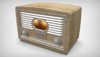
(The image above is a 3D Rendering, updated to the latest version on the thread)

Okay, this project has been on my mind for years now (Even before the Pip-Boy). Every once and awhile I dig around to see what others have done, and how I might go about the project. As with all my projects, I want something very authentic. A functional radio with all the controls working and real speakers.

The radio will share some circuitry with my Pip-Boy project, so it could become an easy build once I have those circuits working.

----------------------

Today, I re-read some of the projects folks have already done:

Today I noticed that Mach posted that the front of the radio is based on a 1938 Zenith 5-2-319 radio. Once you see it, you realize the original game art designer lifted bits and pieces from it and a few other radios.

----------------------

48729485108_c2b8f44302_c.jpg


This radio is well documented online, and so I set about 3D modeling the front bezel on that radio as accurately as possible, omitting only the extra knobs and screws not visible on the Fallout radio. To get the scale of the bezel correct, I looked up a few old eBay listings. I found one that listed the dimensions of the whole radio. (13Wx9Hx7D).

If I scale the Fallout radio to match the bezel dimensions, then the Fallout radio ends up 21.7"x14"x13.7" Not huge, but not as small as I expected. Seeing it next to my other Fallout prop designs makes me want to scale it down to about 14" wide. I may do some printouts and paper mocks up to find a scale that feels correct.

----------------------

48730030707_4f27a65c6e_z.jpg

A few years ago I made a vector art version of the control dial. So I had that ready to go.

----------------------

48729995077_01acf1f055_c.jpg


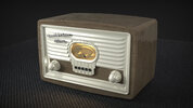
I 3D modeled all of this today. The front has proper louver style vents, and will have two speakers behind the front.
On the Zenith radio, the five black dots were actually for a radio station label to sit, it was one of the first radios with presets. I plan on keeping that function. But the bottom edge of each finger will be flexible and have a tactile button behind it, so it can keep that function without changing the look.

----------------------

48729995047_38c8798883_c.jpg


I love this image, I overlaid my rendering over a in-game screenshot.

----------------------

My plan it to laser-cut plywood for the chassis. Either with a veneer on the outside, or using the age old technique of feathering the back of the plywood to get the curve. The front bezel and knobs would be 3D printed, smoothed and painted. The rear would be real sheet metal. I would use real hardware where possible.

Electrically I plan on using a amplifier kit I have laying around, but the Radio circuit would be all custom. Using a Raspberry pi to control a real radio IC, and provide the ability to play digital files/streams.

----------------------

As usual with me, this is a long term project. I just got to get my ideas logged. I don't know when I will work on this next.
 

Attachments

  • 48729994972_0cf509d16f_c.jpg
    48729994972_0cf509d16f_c.jpg
    76.2 KB · Views: 5,639
  • Render, Radiation King, Game Accurate.jpg
    Render, Radiation King, Game Accurate.jpg
    809.2 KB · Views: 852
Last edited:
Very cool Zap. Let me know if you want to try a cast aluminum bezel. On the back cover, on the actual radios it was usually plywood, pressed paper or masonite with all sorts of fun printed details. Like "This receiver is certified to comply with radiation requirements of the Federal Communications Commission". Metal would have gotten very hot and been an electrocution risk. Arguably, not a likely concern from a company called Radiation King. The 539 actually had an asbestos sheet across the top to protect the wood.

i-hrrQj8x-M[1].jpg
i-KVhD5Qp-M[1].jpg
 
I don't know that the louvers would come out well with casting. they would have to be cast closed, and dremeled open. I want them to be the speaker openings, rather than put them in the back as others have done. In my mind that front panel would have been formed from cheap stamped steel and then painted, it would have to look of an ac vent. After all these radios were mass manufactured.

The back in-game is a galvanized steel panel. But most radios of the time had masonite as you noted.

I am debating how much to make this game-accurate overall, versus something closer to what one would actually look like in real life.
For now I will just provide minimum cutouts on the rear for a power cord and antenna connections.

--------------

48731816067_d8aa9d4514_c.jpg


As far as scale, I actually have the camera seen on the desk in the above in-game shot. I found it as a converted lamp at a local craft show.

The camera measures 3.25" wide. If I scale up the in-game photo that makes the radio 11" wide. I know that Fallout games have the scale all over the place so I have to settle on some number. I guess I will stick to just 12" wide.

Also, if your wondering what that MSA thing is behind the camera, it is a 1950's Carbon Monoxide detector kit from the Mine Safety Appliances company. (They are still in business too). I felt it sort of looked a lot like a stealth boy (granted those had canvas cases)
 
Man, where did you find a old radio with the pre curved sides? I have been to dozens of antique shops without success finding anything even close. Is that the radio you posted in the other thread, modified?

Please do give the dimensions of yours, compared to the camera it is a bit smaller than I imagine making mine. For the front did you use SLS 3D printing? (Shapeways)
 
Hey!

Sorry, I haven't seen you had replied to this! Feel free to tag me, as I don't always re check threads rapidly haha!

The radio I had found was a Philco. However, they appear to be fairly rare, even when I bought mine, there was only one on ebay at the time.

This was the shell of it, when I removed everything and before cleaning it up :

DSC_0107.jpg


I believe it also had the right size for it: 11" x 6.5" and 5.5"deep!
 
YtIT6rd.png


YiZ39C9.png


EmmaInCandyland: Holy cow! Philco made a lot of different models of Radio. But I dug through the whole list. It looks like its a Model 42-PT96, or 46-201 They do appear the be rare. Also, some later Philco radios had louvered openings, this one even has a trapezoid shape too. The Radiation King has a subtle trapezoid shape in the area where it recesses into the radio, I haven't seen anyone catch that small detail yet.

That Philco radio may have been the reference for the in-game enclosure. The back panel of that radio has the same shaped cutouts as the Fallout radio.

So many props in Fallout (and other games) are kit bashed from real-world items. For example, in Metro Exodus, I recognized that one of the parts on the upgraded pneumatic gun was the aftermarket fuel pump on a 1939 Ford Tudor. I only noticed because I had just recently helped my Dad fix that exact item on his friend's old car.
 
This showed up on eBay: A 1942 Philco 42-PT-96. I had to get it.

cKPGJvP.jpg


pCQOTyt.jpg


It has all its guts. No idea if it is functional or not, I need to do some research and cleanup inside before I plug it in. Seller claims it does light up and produce static. I won't be restoring it. Instead, I will modify it to put modern electronics hidden inside. If the tube glow on the A/C power, and the wattage isn't horrible, I will probably let them run, otherwise some amber LEDs can help illuminate them.

For now it will set on the shelf, I have to get some other projects done first.
 
It is wood, but the surface texture appears to be a transfer print. The knobs and guage are bakelite. The rear panel is masonite. I'll take more photos when I take it apart.
 
51386845107_e3ba1c7ce1_h.jpg

The above is a 3D rendering.

So working on the Pip-Boy GUI has resulted in me having a python based radio. So that got me itching to take another look at upgrading my Philico Radio.

-----------------

51387605521_cac93c61fa_h.jpg


I re-did the CAD design to match the Philco radio. My original design was about 30% too large. The plan is to cutout a hole in the front of the radio, and panel mount a 3D printed bezel. Everything will attach to the Bezel.

Inside will be a Rasberry Pi Zero, a Adafruit 3W stereo i2s sound bonnet, a H-Bridge servo drive, and a custom PCB to tie it all together.
The speakers are simple 3W 4ohm speakers that are the same as the mono 3" speaker that was inside this radio originally.


-----------------

51388339799_432651ac01_h.jpg


The illumination for the radio gauge will be via a neopixel warm-white LED strip. (I can also do colors)

-----------------

51387852803_6988fe5790_h.jpg


The radio gauge will be driven by a automotive gauge servo. This allows me to use a custom needle and I don't have to hack some analog meter and I will have more precise control.

The five super-tall tactile switches make contact with the back of the five buttons just below the gauge.

-----------------

51388353929_5daa581396_c.jpg


Regarding the gauge display. The game designers use a variety of radios as reference.(mentioned in the thread above). It wasn't until I had an old analog amp meter that I realized what the lighter portion of the gauge was. It isn't a printed paper display. It is a brass gauge with a mirror finished middle. On old meters they left a portion of the meter with a mirror finish that makes reading the needle easier.

So I plan on making the meter display using a acid etched brass plate.

-----------------

51386845347_56ca242b35_h.jpg


The plan is to keep the original electronics inside the radio, just shoved a bit closer to the back panel. That way the insides still look authentic.
I am not sure yet if will try to light up the vacuum tubes. They supposedly glow already if plugged in, but plugging in old radios without prior repair is a good way to kill them and dangerous. So if I light them up it will be via some LEDs.

-----------------

51386845422_267d6112b1_h.jpg


One thing I love about my radio is it was made when a UL-rating was still a new concept.

-----------------

For now I will be collecting all the parts for this build.
 
So this weekend I ended up prototyping all the electronics and most of the software for this project. (Video coming soon).

In the code I am automatically parsing the radio stations just like in the PIp-Boy code,. The difference is that I want to simulate an analog hand tuned radio, including static sounds between the stations.

I evenly distribute the "location" of all the radio stations across the dial. Then using a potentiometer the user can control the location of the guage dial. Static is played until you get near to a radio station, at which point both the station and static play at the same time. As you get closer to the actual location of the station on the dial, the radio station gets louder. Then once your right on the station location, the station plays in the clear with no static. It ends up being a pretty accurate effect. You even get the hint of a station playing if you move the dial quickly, and have to back track and fine tune to get just the right spot.

Below is the code for just the tuning portion:
Code:
def tuning():
    global stepper_target, stepper_location, snd_static, volume, total_station_num, prev_tuning_station, active_station, tuning_volume, tuning_sensitivity
    nearest_station_num = int(expand(stepper_location, 0, stepper_steps, 0, total_station_num))
    station_position = int(expand(nearest_station_num, 0, total_station_num, 0, stepper_steps))

    # if stepper_target != stepper_location:
    #     print("Stepper location =", stepper_location, "Stepper target =", stepper_target, "station_position=",
    #           station_position)

    range_to_station = abs(station_position - stepper_location)

    if range_to_station <= tuning_sensitivity / 3:  # Play at volume with no static when needle is close to station position
        if active_station and tuning_volume != volume:
            print("Locked to station #", nearest_station_num, "Position:", station_position, "Needle=",
                  stepper_location, "sensitivity =", tuning_sensitivity / 3,)
            pygame.mixer.music.set_volume(volume)
            tuning_volume = volume
            if pygame.mixer.Channel(1).get_busy():
                pygame.mixer.Channel(1).stop()

    elif range_to_station <= tuning_sensitivity / 2:  # Start playing when the needle get near a station position
        if not active_station:
            print("Near station #", nearest_station_num, "Position:", station_position, "Needle=",
                  stepper_location, "sensitivity =", tuning_sensitivity / 2,)
            tuning_volume = volume / (range_to_station / settings.near_volume)
            select_station(nearest_station_num)
        else:
            if not pygame.mixer.Channel(1).get_busy():
                snd_static.set_volume(volume / settings.static_volume)
                pygame.mixer.Channel(1).play(snd_static, 255)
            else:
                snd_static.set_volume(volume / settings.static_volume)

            tuning_volume = volume / (range_to_station / settings.near_volume)
            pygame.mixer.music.set_volume(tuning_volume)

    else:  # Stop any music and play static if the needle is not near any station position
        if active_station:
            print("Stopping active station. Nearest station # is:", nearest_station_num, "Position:", station_position,
                  "Needle=",
                  stepper_location)
            active_station.stop()
            pygame.mixer.music.stop()
            active_station = None
            tuning_volume = volume / 4
        if not pygame.mixer.Channel(1).get_busy():
            snd_static.set_volume(volume / settings.static_volume)
            pygame.mixer.Channel(1).play(snd_static, 255)
 
Mate this gets more and more exciting! It has been quite a while since I have last checked on this thread, it has been progressing! I must admit its nice seeing others using my own radio build as reference :) Seeing all this new progress that you have done does make me want to build a second version that has way more functionality than the first. Looking forward to what you will be doing next! Cheers
 
51562864259_02891c7a10_k.jpg


I have actually been working on this a lot in the past few weeks. I just have not posted anything since it is mostly code work.
I did 3D print the badge for the radio though. The badge has arms that slide behind the vents to hold it in place. It will get a chrome like finish.

I had to change from using the Automotive servo gauge to back to air-core motor gauge I am using in the Dosimeter and Pip-Boy. The servo was just way too jittery, with discrete steps visible as it moved. The air core moves as smooth as can be and is just much closer to the look of an old radio. I have all the tuning and playback working great now.

-----------------------
https://www.artstation.com/artwork/9eNeOa
pavel-nowski-screenshot000.jpg


The coolest development is what I am working on now. You see I wanted the Radiation King Radio to have a remote control. But I wanted the remote to feel like it was from the Fallout universe.

I googled "Fallout remote" and didn't find any official props, but I did find this amazing 3D rendering made by Pavel Tornowski. He made it as part of the yet unfinished Fallout New Miami mod.

-----------------------

51563109745_8f322e856a_k.jpg


The remote he based it on is real! This is the Zenith Space Command 4-button remote control. The model I got is in like new condition with an great chrome finish. Amazing considering this was manufactured sometime in the early 1960's.

It is one of the very first television remote controls ever released. I knew this thing worked using Ultrasound and not Infrared when I ordered it off eBay. I thought it used an electronic emitter, and I expected to swap out the guts for a modern IR based microcontroller based remote.

---------------------

51562182246_21d093baa7_k.jpg


However, this thing is actually purely mechanical. I will do a video on just this soon, but here is how it works: When you press the clunky button on top, it releases a spring loaded hammer that smacks the bottom of an aluminum rod. This rod vibrates at an ultrasonic frequency. This is then picked up by a high-frequency microphone on the TV using a vacuum tube circuit and the TV responds to the remote command.

While I could still put electronics and switches inside, I decided not to modify this beautiful bit of history. Instead I repaired a few of the loose aluminum rods, and put it all back together.

----------------------------------------------

I am now working on the software to decode the four signals electronically.

At first I tried to use a i2C ADC and the Raspberry Pi Zero, but the ADC wasn't fast enough to clearly separate the ultrasonic signals. So instead I am using a RP2040 which has a ADC that can run at nearly 500 MHz. This allows me to pick up the signal without too much trouble.

I am using CircuitPython and the uLab library to perform a Fast Fourier Transform (FFT) on the ADC samples. This lets me discern between the four different frequencies. Currently I am not actually figuring out the exact frequencies, instead I just care about detecting the four buttons. So I just do a spectrogram and determine if the signal is between a set of addresses. It works for the most part but still needs some work to be 100% reliable.

I have only found one other person online who tried to modernize a Space Command remote, but he just stopped at just detecting any sort of ultrasonic signal instead of determining which button was being pressed. As far as I can tell I am the first person to try to get it working as a 4-button remote using modern electronics.

I did have to shorten one of the rods, as the frequency separation on one of the rods wasn't very large.
 
Last edited:
I have finished my python code for everything but the above Ultrasonic Remote Control.
(Video coming soon)

The simulated live playback and virtual frequency bands were the trickiest aspects to get working,

The virtual radio bands are actually necessary as you have the same limitations that a real radio. There is just only so much room on the dial for stations to sit next to each other. I have found a dozen stations to work well.

Currently I have the following virtual frequency bands: Fallout 4, New Word Radio, Audio Drams, and Test Files. Each has between 4 and 8 radio stations. The software automatically parses new folders and files. Other than converting files to .OGG, adding new music is really simple.

I plan on adding Fallout 3, Fallout 76, and a Jazz station to my radio before I am done. I have both extracted the music from the game, as well as downloaded publicly available songs to fill up the stations. I even have a big station with over 600 songs that works great.

Here are all the features I have managed to cram in:
-Simulated live radio station playback
-Multiple virtual radio frequency bands
-Authentic fuzz and tuning sounds
-Automatic parsing of folders and audio files
-Automatic distribution of the radio stations across an analog dial
-Cached metadata for faster handling of large libraries
-Analog Air Core Motor control
-Potentiometer and Rotary encoder inputs
-Manual button activated tuning
-Manual song skipping
-Playback ordered or randomized stations
-Standby mode

If you want to check out the code, I have pushed it to GitHub:

GIT hub only has the test audio files setup as a template. Before you can use it you need to add your own music.

Keep in mind I am still very much learning Python, and much of the code is just in one file and specific to my hardware.

Here is a list of the components I am currently using:
-Raspberry Pi Zero W
-Pimporoni BTN Shim
-Adafruit speaker bonnet
-Adafruit PCF8591 ADC
-Potentiometer with switch (Connected to the ADC)
-SparkFun Qwicc Motor Driver
-Adafruit i2c QT Rotary Encoder
-Adafruit NeoPixel Stick 8x, Warm White
-Simco 2022-716 Air Core Motor

While there are plenty of GPIO pins on the Pi I could use for the rotary encoder or other functions, I am trying to stick to a completely i2c input method such that I can integrate these same circuits and code into the Pip-Boy.
 
However, this thing is actually purely mechanical. I will do a video on just this soon, but here is how it works: When you press the clunky button on top, it releases a spring loaded hammer that smacks the bottom of an aluminum rod. This rod vibrates at an ultrasonic frequency. This is then picked up by a high-frequency microphone on the TV using a vacuum tube circuit and the TV responds to the remote command.
That's fascinating, never had any idea that old remotes worked that way....
 
So I ran into a issue that took me a long time to solve. I was about to start the PCB design for this, but then realized that the SparkFun i2c motor controller didn't use a simple i2c chip, but a 48 pin Cortec processor with custom firmware. Which meant I couldn't easily drop it down on a PCB.
I was also using a i2c ADC for the potentiometers, and i2c GPIO expander for the buttons. The goal being to keep all the peripherals on the i2c bus.

In the end I decided to convert everything over to just a Pi Zero, and Pi Pico. The Pico handles all the buttons, LED, Motor and analog in/out. It has enough GPIO pins to do everything needed. I had to convert about half of the firmware I had written on the Zero to run on the Pico. Fortunately the Pico can run CircuitPython, so this wasn't too painful.

What was a pain was getting the motor controller working. The SparkFun controller worked perfectly with the Air Core motor, but suddenly the TI chip I was using went slow near 0 and 90 degrees. After much research I realized I needed to use a different controller. One which had separate coil polarity control and PWM input. This allows the coils to not only go from zero to full voltage, but also reverses that voltage. Keeping a strong magnetic field regardless of the angle.

I am about 90% done with the software for this. I have uploaded the code so far to Github: GitHub - zapwizard/radiation_king_radio: A pygame based radio player with some unique radio band and live playback features.
I still need to add some code to sync up the startup events and settings. Ideally where I can update the Pi Pico firmware from the Pi Zero instead of over USB.

Regarding the Ultrasonic Remote control:

486c5b874b0cc0deb6cebc7d523efff4.png


I designed my first personal project PCB! (Not counting all those homemade PCBs from projects past)
You see I was trying to use a hacked Ultrasonic range finder as the receiver for the Ultrasonic signal.
The remote sends out signals between 40kHz and 37kHz. The range finder runs at 38kHz. But the range finder also has a bandpass filter, and the actual ultrasonic transducer is only sensitive around 38kHz.

I managed to get the ADC on the RP2040 running fast enough to perform a FFT on the signal by using C++ code, but the results aren't consistent enough to be useful. Two of the buttons would give a good signal about 25% of the time, but there was a lot of noise and sideband signals that would confuse the results. And two of the button would only be picked up if the remote was within a foot of the receiver, making it useless.

After a lot more research I decided I needed an Ultrasonic microphone. You can buy a USB ultrasonic microphone, but they are expensive and bulky. I then learned about PDM microphones. These are mics with a digital audio signal output, and CircuitPython and the RP2040 both handle PDM audio as an input.

I hit up Digikey and found the SPH0641LU4H-1 Mems Microphone. It is a tiny chip that can handle a signal from 100Hz to 80,000 Hz! All while using PDM audio which means I don't need to sample a ADC at high speed to get a useable set of data. So I went ahead and designed a breakout board for the microphone. It should arrive in a few weeks. I will release the design files for it once I validate the board works.
 

Your message may be considered spam for the following reasons:

If you wish to reply despite these issues, check the box below before replying.
Be aware that malicious compliance may result in more severe penalties.
Back
Top