You are using an out of date browser. It may not display this or other websites correctly.
You should upgrade or use an alternative browser.
You should upgrade or use an alternative browser.
Y-wing... Why Not... SS Y-wing Build by mjhenks.
- Thread starter mjhenks
- Start date
Tonight was most frustrating. I take my hat off to those who blazed the trail.
I would describe it as working on a puzzle with a partial picture and half the parts.
I think I need to just start gluing pieces on and see what parts I do not have. Then decide how to close the gap.
But I’m preaching to the choir.

I would describe it as working on a puzzle with a partial picture and half the parts.
I think I need to just start gluing pieces on and see what parts I do not have. Then decide how to close the gap.
But I’m preaching to the choir.
Last edited:
So lets start the puzzle for real. Since my build must have a R2 unit my first order of business was to make that happen.
Let's get Crazy folks and totally machine off the top of the ship to start with. What???


I needed to make room for the R2 socket. My Nurnie kit had the Red Jammer top so i had to make that work. I could either pocket out the RJ molded part or cut off the top of my model. You already know what i did.
Now to remove what i think is a B-29 top turret and re-form it to fit an R2 unit.


I did not get a finish shot before it was installed. Before that i also had to trim down the side Nurnies.
I used or 1/2" forstner bit to drill out the arc for the wing strut and then milled the part down to size. Worked great and fits great. Below is before i trimmed down to size.

Let get real and use some glue. First the finished R2 socket and then the progress for the evening. Everything is glued in place. I will clean up the glue later.


I started with the top as i could ID more parts up there. I am really struggling to ID all the parts in the Nurnie kit. Hard to tell if they are simply not there or cut down so much to not be easily recognized. I think it is a little of both. Once i get everything i can ID in place i will reach out for help with what is left.
Anyways...
Let's get Crazy folks and totally machine off the top of the ship to start with. What???
I needed to make room for the R2 socket. My Nurnie kit had the Red Jammer top so i had to make that work. I could either pocket out the RJ molded part or cut off the top of my model. You already know what i did.
Now to remove what i think is a B-29 top turret and re-form it to fit an R2 unit.
I did not get a finish shot before it was installed. Before that i also had to trim down the side Nurnies.
I used or 1/2" forstner bit to drill out the arc for the wing strut and then milled the part down to size. Worked great and fits great. Below is before i trimmed down to size.
Let get real and use some glue. First the finished R2 socket and then the progress for the evening. Everything is glued in place. I will clean up the glue later.
I started with the top as i could ID more parts up there. I am really struggling to ID all the parts in the Nurnie kit. Hard to tell if they are simply not there or cut down so much to not be easily recognized. I think it is a little of both. Once i get everything i can ID in place i will reach out for help with what is left.
Anyways...
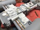
Went farther than i thought i would this weekend. I purchased a huge surplus lot of KnS metal about 3 months back. Solid & tubes. Aluminum, brass & copper. Started playing with it and tried my hand at piping the top. I am OK with the results but need a better bender. I still have Nurnies to ID and find but that will come.


I backed myself into a corner. I planned to finish the cockpit proper and mate the two halves together. I then discovered that i cannot install the cockpit because of the fiber optics. (FO) I should have seen that coming. (I am kicking myself now)
I can get around that. It is cumbersome but do-able.
The real problem is that things are not fitting. Nothing to do with the FO's. When i place the cockpit proper (CP) into the lower body and install the upper body the CP alignment to the upper half of the cockpit is great. The issue is a huge gap between the upper and lower cockpit body. The seam is at least 3/16". (Forgot to get image)
The CP is too tall or my 3D printed cockpit body is too short or not curved enough. When i clamp the halves together a decent gap forms between the CP and upper body. I have already shaved down the CP and made sure the lower half body is flat to mount the CP. Not sure what the problem is but anyone else face this?


I fear all my FO has to be removed or my body piece re-printed. I know it is part of the game. Just frustrating.
Any thoughts?
I backed myself into a corner. I planned to finish the cockpit proper and mate the two halves together. I then discovered that i cannot install the cockpit because of the fiber optics. (FO) I should have seen that coming. (I am kicking myself now)
I can get around that. It is cumbersome but do-able.
The real problem is that things are not fitting. Nothing to do with the FO's. When i place the cockpit proper (CP) into the lower body and install the upper body the CP alignment to the upper half of the cockpit is great. The issue is a huge gap between the upper and lower cockpit body. The seam is at least 3/16". (Forgot to get image)
The CP is too tall or my 3D printed cockpit body is too short or not curved enough. When i clamp the halves together a decent gap forms between the CP and upper body. I have already shaved down the CP and made sure the lower half body is flat to mount the CP. Not sure what the problem is but anyone else face this?
I fear all my FO has to be removed or my body piece re-printed. I know it is part of the game. Just frustrating.
Any thoughts?
Welcome to our world!!!
Studio Scale Model Building: 99% frustration and Oh, that 1% Sweet Spot that we get to hit just every so often.
But yeah: what you're discovering is the hard truth: nobody has yet nailed the armature specs (or produced a complete 3D CAD file thereof that they are sharing), so a lot of shimming, gap-filling, and overall "body work" is required to make it look Y-Wingy.
Still, yours looks really good, and will soon be great.
dtssyst
Sr Member
Does the upper forward fuselage fit the lower without the cockpit?
Do they not seal properly only when the cockpit with fo is in place?
If they fit without any issues with no cockpit, then just redo the fo.
My build was all self enclosed in the underside of the cockpit. Only a wire to connect to the power source was all that protruded. Part of the side of my cockpit was cut out to allow room for that wire (+&-).
Is that the greeblie kit from Studio Kitbash?I am really struggling to ID all the parts in the Nurnie kit. Hard to tell if they are simply not there or cut down so much to not be easily recognized. I think it is a little of both.
Did some more looking this AM. I need to shave off 3/16" from the cockpit bottom. In test fitting it off of the armature it seemed to fit OK but once mounted to the armature it is not. No big deal but frustrating. Part of me wants to re-do the FO but the other parts says never again. ")
So far i have only bought the Saturn V kits. SK told me ahead of time his nurnie kit was not complete and he spent alot of time getting me up to speed. My plan right now is to build as far as i can with what i have (without blocking parts of the body) and then evaluate how to source the rest. (3D print from existing files, Design my self & 3D print, scratch build, casting or the real deal...) It is all time vs Money.
Yes. It is one of Studio Kitbash "seconds" kit. I also got a small batch of parts from another builder too who will remain anonomous. The Cockpit and R2 unit are from Gus76.Is that the greeblie kit from Studio Kitbash?
So far i have only bought the Saturn V kits. SK told me ahead of time his nurnie kit was not complete and he spent alot of time getting me up to speed. My plan right now is to build as far as i can with what i have (without blocking parts of the body) and then evaluate how to source the rest. (3D print from existing files, Design my self & 3D print, scratch build, casting or the real deal...) It is all time vs Money.
Lots of carving last night. Got 90% the way there. Had to remove ~3/16" from the bottom of the cockpit itself, removed all gussets and ribs plus the sides of the torpedo tubes from the cockpit bottom plate and about 3/16" from the cockpit rear detail plate. I also had to move some FO lights around.
As it sits now the cockpit halves mate well enough but the cockpit itself still sits about 1/32 high with a small gap. It is hard to see what is causing the gap but still working in out. The bottom image is about where i finished up. I did not grab an image of the final fitment.
Thank you for the encouragement.
After shaving and cutting everywhere and after taking the cockpit back apart i finally found my solution. I needed to drop the cockpit another 1/16" to get it to sit right in the shell and i was afraid to shave any more off of Gus76 cocpit bottom. He would be ashamed of what i have done to his good work. At least all my sins will be hidden.
I started probing with my dremil on how hard it would be to lower the floor of the bottom half. That was the hot ticket as i discovered the 3D print was not a solid layer but two layers seperated by fill. Cool.
Soooo.... Lets tub this thing.
I removed the entire upper layer of the 3D printed lower cockpit half. It was actually quite easy to do once i figured it out. Using a Dremil i cut the boarder of the area i need to strip and then with a X-axto knife pealed the top layer up. Wala...
The problem.

The solution.


It fits now!

I am now in the process of re-building my FO as they got really messed up in this whole adventure.
A new car project (1969 Riviera) also has me a little distracted so the next few weeks may not be as productive but i am sure i am not the only one who has more than one iron in the fire...
I started probing with my dremil on how hard it would be to lower the floor of the bottom half. That was the hot ticket as i discovered the 3D print was not a solid layer but two layers seperated by fill. Cool.
Soooo.... Lets tub this thing.
I removed the entire upper layer of the 3D printed lower cockpit half. It was actually quite easy to do once i figured it out. Using a Dremil i cut the boarder of the area i need to strip and then with a X-axto knife pealed the top layer up. Wala...
The problem.
The solution.
It fits now!
I am now in the process of re-building my FO as they got really messed up in this whole adventure.
A new car project (1969 Riviera) also has me a little distracted so the next few weeks may not be as productive but i am sure i am not the only one who has more than one iron in the fire...
Joining the cockpit time.
Painted my FO flat black to cut down stray light, checked the lighting one more time and went for it.
Ended up with some rather large gaps.
Some super glue, filler, sanding and my ship has a nose. I still have some finish body work to do and will have to touch up the cockpit here and there.


Painted my FO flat black to cut down stray light, checked the lighting one more time and went for it.
Ended up with some rather large gaps.
Some super glue, filler, sanding and my ship has a nose. I still have some finish body work to do and will have to touch up the cockpit here and there.
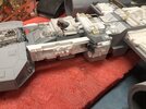
Nurnies on the bottom.

Nurnies and piping on the neck


Starting the cockpit over again


I should have seen it. The struggle I had with the cockpit fitting and how much I had to shave off was the warning. That left the cockpit too short as seen by the neck piping.
I almost said “screw it” and soldered on but some sage advice was offered and I tore it back down.
Bummer...
Nurnies and piping on the neck
Starting the cockpit over again
I should have seen it. The struggle I had with the cockpit fitting and how much I had to shave off was the warning. That left the cockpit too short as seen by the neck piping.
I almost said “screw it” and soldered on but some sage advice was offered and I tore it back down.
Bummer...
Attachments
New cockpit. Fitting things relative to the horizontal pipes to the rear of cockpit. Obviously I have issues. Befor I glue up and fix the issues...
[mention]Studio Kitbash [/mention], [mention]dtssyst [/mention] Does this fit look right?
These are the stock DaveG cockpit files with an improperly trimmed rear detail resin piece. Not the gap at the bottom seam.


And of course making these new cockpit parts.

[mention]Studio Kitbash [/mention], [mention]dtssyst [/mention] Does this fit look right?
These are the stock DaveG cockpit files with an improperly trimmed rear detail resin piece. Not the gap at the bottom seam.
And of course making these new cockpit parts.
So are you using filler primer on these prints and just re-scribing the panel lines? Looking good btw!
SB
SB
Similar threads
- Replies
- 150
- Views
- 16,703
- Replies
- 2
- Views
- 460
- Replies
- 3
- Views
- 632
- Replies
- 11
- Views
- 1,553
- Replies
- 12
- Views
- 1,263