Y-wing... Why Not... SS Y-wing Build by mjhenks.

mjhenks

Sr Member
RPF PREMIUM MEMBER
With some coaxing from Studio Kitbash and dtssyst i will add to the SS forum my Y-wing build. My plan is to head in the direction of Red Jammer but this being my first SS model know i will not hit it 100% and i am OK with that. My background is R2 building and really building anything. Cars, Home, machines, toys, etc. Just never SS models. A few years back i built a Jedi Training remote that turned out great util the paint job. That is my weakness. I suck in fact! I have all the tools but none of the skills. It is really weathering that i suck at and fine detail painting. I have owned a Pyro X-wing kit and SS Tie kit for many years but always been too chicken to try. Mainly because the eventual paint job. I hope this project gives me the confidence to do the other two.

IMG_7248.JPG


IMG_7249.JPG


I took the leap because of Dave G's work. Thank you Dave. That and the help from many other's have kept me going. I am actually already well down the road but i will start at the beginning and catch up instead of posting "boom" here i am.

Hope the journey goes well.
 
Last edited:
Based on your Training Remote and R2-D2, I'd say you're going to be Just FINE building a Red Jammer.

First of all, the Y-Wing is very forgiving because no two are alike. Second of all, the Red Jammer is super-messy to begin with, so the worse you do, the better it ends up looking... from a certain point of view.

And the joy of it is the real reason for building, and the build is the journey, not the destination, and it's in the learning curve that all the fun and excitement and discovery happens.

Finally, there are at least three or four guys on here who are EXCELLENT painters AND who offer their services for a reasonable fee. I will leave it to them to self-identify, but they know who they are. So if the painting/weathering really scares you, don't worry about it and look at the build thread of someone whose Y you like, and ask them if they'll give you a quote for the final paint job.
 
With any new project i started out reading all i could. Dave G's Green Leader project read was the start and that branched into a bunch of other threads and learning. I knew i was not going to collect all of the original model kits for this. I have a Ultimaker 2+ so it was going to be a combination of printing and buying cast parts.

I have to say the information collected in Dave's thread was a huge push in realizing this could be done. Thank you for all those who took the time to post.

First decision was where to get all those neato greeblies. (or nurnies. Use which you want) Studio Kitbash came highly recommended for his Nurnie set so i went that way. That also set my course for 3D printing. I found the Red Jammer build by dtssyst decieded to use the stretched version of body parts instead of the originals. That started many, many days of printing starting with the cockpit. No images of the raw prints. Only after i started and finished body work.

IMG_6563.JPG


IMG_6824.JPG


IMG_6819.JPG
 
Last edited:
That top picture made me do a double-take as I thought you'd made your cockpit head piece out of wood! Had to look twice to realize it was a 3D print.

Ya. Looks that way. Just the first or second sand down after primer to fill the layers. I like to alternate primer color between red and grey to see the layers. An old auto body trick.
 
After days of printing and doing the body work on each part i ended up with a pile of parts.

You will notice my finished "Legg's" in the shot, armature parts, some Tee rails and Saturn V parts. Remember i am catching up. I'll get to those later.
You can also see my pre-production R2D2 Lightsaber door there too. Another project

IMG_6942.JPG


Machined up the Armature parts. The Aluminum rod i left long for now and without the front cockpit holes.

IMG_6839.JPG


Milling the 1/2" rod. For this i took a solid rod and drilled holes from each end 80% to the center. I then milled an access pocket into the center that would interface with the 3D printed body mount and allow wires to go to the wings.

IMG_6855.JPG


The "wings" were next. This was made from 1/4" Lexan and i extended the front out 5mm to adjust for the extended body 3D printed parts. I first cut this out with the band saw and then milled all the edges flat and put the holes in. This image is when i went back to trim the ends to fit into the engine mounts.

IMG_6952.JPG


Each 3D body part i tried to choose an orientation to minimize my body work. Sometimes i had to go back and mill parts flat again. This was where the 3D supports were and i need this flat to mount to the main armature rod. I'm lazy!

IMG_6854.JPG


Test fitting. A Keen eye will notice that these parts do not match what i have shown above. For instance the "wings" are different. Well i made some mistakes and more or less build two complete bodies. It was a bummer but i learned. This is actually body #1 as i do not have a full image of the test fit of body #2. (This body is actually fully finished now with electrical and not bad but not what i wanted)

IMG_6627.JPG


Test fitting body #2. This area was trouble. The 1/2" rod would break the plastic when inserted. Re-made this part a few times and finally got it together and glued the crap out of it.

IMG_7049.JPG


IMG_7048.JPG


IMG_7054.JPG


That is today's catch-up post.
 

Attachments

  • IMG_7055.JPG
    IMG_7055.JPG
    3 MB · Views: 125
Last edited:
Time to fit the engine mounts and modify the Saturn V Body parts to fit around. I ended up purchasing two Arfix Saturn V kits (the new mold version) at a decent price.

Fitting the engine mounts.

IMG_6953.JPG


IMG_6954.JPG


Modification of the Saturn body to fit around the armature wings.

IMG_7039.JPG


IMG_7043.JPG


Battle damage. here we come.

IMG_7041.JPG


IMG_7042.JPG


IMG_7045.JPG


I think i can live with the battle damage but we will see once i start applying details. I can always fill it and sand it smooth.

Engines fitted. Will glue them later.

IMG_7044.JPG
 
Last edited:
Body assembly and wiring.

The body has good routing channels for the wires to the cockpit and the wings. I made a few modification here and there to aid routing but for the most part it was clean to begin with.

IMG_7069.JPG


Biggest area of change was at the front body cap. I machined a slot to pass the wires into the aluminum strut channel here.

IMG_7070.JPG


Here is how the wires passed into the rear bar slots under the main armature rod mount.

IMG_7072.JPG


After that i glued all the pieces in place and started body work to hide the seams. Evercoat Z-grip, 80 grit sand paper to sculpt, Prime, sand, repeat.

I suspect that the detail parts would have hid all of the seams but...

IMG_7073.JPG


IMG_7104.JPG


IMG_7106.JPG


It now looks like one piece. I have not yet mounted the Saturn V engine body piece. Also note i still have not shortened the aluminum armature or put the cockpit holes in. The long rod makes it easy to do the body work.


IMG_7109.JPG
 
Still catching up here.

Engine work. They are made from 3D printed parts & machined parts and the base which is from the Saturn 5 kit.

This part was fun. I was not happy with the available 3D files so i made my own. I tried a few version to get the "wire loop" on the Sea Lab part to work out but was not happy. In the end i 3D printed wire integrated that and it worked.

Below is the evolution and final assy. I started with the Sea Lab crane and metal wire. Then went to the integrated printed wire with integrated flaps. I ended up with integrated wire and separate flaps as shown at the bottom. The finish work here was tedious as not to break the printed parts.

IMG_6828.JPG


Vane housing and pistons. I have to live with printer strada here as this part was hard to sand smooth. I do not know the origin of the piston holders so have not thought about making this from scratch yet.

IMG_6830.JPG


Engine body.

As printed and then finished. I had to turn down the end to fit into my custom designed and printed exhaust nozzle. I was not happy with the had carved turkey feathers so i designed my own in nozzle and printed it up.

The two color print is what you have to do when you run out of filament mid run. Jam a new spool in there and continue on. Had to stand over the printer and monitor progress. When the drive wheel ran through the grey I shoved the black in there without loosing printer pressure. It worked and looks cool.

IMG_6825.JPG


IMG_6858.JPG


IMG_6840.JPG


IMG_6842.JPG


Every engine needs a nice red light. I really liked how Flyscriber did his engines so after talking with him i did similar. I designed an adapter to go into the existing engine housing and hold the 3/4" Red Acrylic rod after i shaped and polished the end of it. Worked out nice.

The lighted sample is using my flashlight. I am still looking for LED's to do the same.

IMG_7063.JPG


IMG_7065.JPG


IMG_7066.JPG


Then onto the Legg's. I am pretty sure i messed these up and will have to re-do them. I notice in the original models the curve of the shell does not end up tangent with the engine body. It is more at an incident angle. To that end even though i cut my shells to the 69.5mm OD they do not present that angled look. Not sure if i should ignore this or not. What do you all suggest?

In case your wondering i filled the inside of the egg with Evercoat Z-grip body filler. Lesson learned here. You have to scratch the heck out of the inside of the egg shell or the filler will pop right back out. I did not do that so i had to glue my filler back into my egg.

IMG_6831.JPG


IMG_6950.JPG


IMG_6832.JPG


IMG_6857.JPG


IMG_6943.JPG


R2D2 standing Guard. Some parts arrived from Gus76 & DaveG. I'll get to them soon.

IMG_7226.JPG


Almost caught up.
 

Attachments

  • IMG_7082.JPG
    IMG_7082.JPG
    2.5 MB · Views: 121
Next catch-up post. Lets work on the struts. Pretty straight forward here. Cut them to length and mill out a pocket to fit under the shocks in the engine fin assy.

IMG_6947.JPG


IMG_6949.JPG


As alluded to in the last post i was able to get my nose cone clips from DaveG. They were super clean and saved me some time. Just had to take the flashing off which was easy.

IMG_6945.JPG


Up next will be cockpit armor plating, front guns, mounting Saturn V motors and Fiber optics. Almost caught up.
 
Today's catch-up post. Engine housings & Armor Plating and guns.

Mounting the Saturn V engine housings was a big step. This is the first real part to go on that will be totally visible. I did some fitting first to make sure the slot and seams were OK.

The milling i did earlier for the slot was at the wrong angle so i went back and hand filed the cuts for the right wing angles.
I also had to file away some areas to make sure the seam fit. A little super glue and lets go for it.

IMG_7217.JPG


IMG_7220.JPG
++
IMG_7216.JPG


Some body filler, sanding and primer and everything looks good.

IMG_7235.JPG


Armor plating. Another first and what a difference this makes. It added so much dimension to the cockpit. I used .040" polystyrene.

IMG_7113.JPG


IMG_7224.JPG


IMG_7225.JPG


Next up was guns. I used KnS brass, copper and aluminum tubing and glued them together. I think i messed up on one of the sections and did not space it right but i am pleased. I also made up a mount for it in the cockpit. I sure hope they are sighted right. :)

IMG_7231.JPG


IMG_7242.JPG


IMG_7241.JPG


This pretty much catches me up to what i have been working on for the last week now. Fiber optics. Never done this before and it shows. Will share that odyssey starting tomorrow. It starts with a bunch of very small drill bits...

IMG_7250.JPG
 

Attachments

  • IMG_7110.JPG
    IMG_7110.JPG
    1.3 MB · Views: 134
That's coming along nicely. Yes, getting the Saturn V shells to fit can be a little fiddly. Looks great!
 
Thank you for the comments. I will be slowing down here pretty quick as today i catch up with real time. My Nurnies are on the way so that will be the next big focus after electrical is all done.

Today's update is cockpit work and fiber optics.

I have never done FO before so this was an experience. A frustrating, eye's blurred and unfocused experience. I am pleased but by no means is it i a great job. I leaned off of dtssyst for this one and am grateful for his pictures. Also grateful for good relationships with the machinist at work who loaned me his set of micro drills knowing i would break some. In the end four .012" drill bits were broken while drilling some 45 holes. Not bad.

I also decided that i wanted multiple light sources and colors. I went with solid white, flashing on/off white and one each of random Blue, Red & White lights. Sort of a way to depict what the many buttons might be doing in real life. Probalby overkill and if scaled up a concocphany of distraction for the poor pilot.

The tools. The purple one is the main bit used.

IMG_7250.JPG


IMG_7251.JPG


IMG_7258.JPG


IMG_7257.JPG


The results of hours of tedious work and four broken bits. I drilled out every button but in the end after paint is done i may not have them all working. Especially as i have broken a few FO's already and do not want to replace them.

IMG_7261.JPG


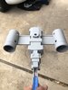
Starting to wire it up. (Is that even the right way to say this?? It is not wire after all...)

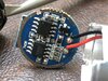
I am using fiber and lights from user me80 on ebay. (Tell him i said hi) He is close by, VERY helpful and had good prices. I used .25mm, .5mm, .75mm, 2mm and 3mm fiber and seven light sources. In reality i have hole for .25, 2.0 & 3.0 but found it sometimes easier to run multiple size FO into the larger holes so i combined what i had. If i did this again i would not use the larger sizes. Probably .25, .75 & maybe 1.0mm.

I plan to run these all off of 12VDC. I am going to ditch the battery power and use 110V instead with a step down to 12VDC (Using a wall wart) and then put inside my base a DC-DC converter to step down to 3.5VDC for my engine lights which will use CREE LED's. So I will run a hollow 5/6" tube for a stand and run two sets of wires into the body. I will put a connector on this so i can remove the model from the base. (More on that later)

The test shots below are running at 18VDC. Why?? because that is what my el-cheapo wall wart that says 9VDC really outputs. It seems that every wall wart i have saved up over the years overdrives the voltage massively.

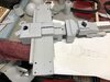
Anyways. On to Fiber Optics. You will see that i carved up the cockpit from Gus76 to route the FO and lighting. It was easy to do but i had to repair a few places when parts i did not mean to remove chipped off. Nothing you would ever see but... I also decided that not all my main cockpit gages will be illuminated. I got tired. I will place back into them hand painted gauges of some sort.

IMG_7272.JPG


IMG_7276.JPG


Now where the mistakes start to come. I got the bright idea to heat shrink the FO into the light source. The issue is that i have an industrial heat shrink gun and lets just say small diameter FO melts faster than heat shrink. I sort of melted them all. I was really pissed but after some testing i realized all the FO while wildly miss-shaped all had light integrity. Disaster averted. You can see i list a few FO's but i am OK with this.

Also for the large 3mm FO's. I purposely heated them to perminantly bend them around the nose of the cockpit. Otherwise they would not make the turn or put too much stress on the cockpit. In the end it all worked out.

I also realized after the fact that the light power wires (black & red wires) were too far back and would not fit in the nose. I simply drilled holes in the sides of the cockpit printed assy and routed the power wires inside the back of the cockpit where i could solder them together and add a single point of electrical contact. I will put a 2 pin connector on that later.

IMG_7291.JPG


IMG_7296.JPG


IMG_7306.JPG


The test. Honestly my dash lights are WAY overpowering. I may stick a resistor on that LED source to cut down the voltage. Once i get the correct electrical set-up installed and tested i will adjust if needed. Also since i have not cut off the FO flush yet many of them are not visible since the FO is off in some random direction.

Again my first try so i am not too displeased. First shot is in the dark with my phone flash going off. Looks good. Second shot is without flash.

IMG_7305.JPG


IMG_7302.JPG


Next up will be the CREE LED engine lights. The goal is to get really bright and solid engine lighting through my red acrylic rod and not see a LED light source but a flood of red light. Hence using the CREE LED.

I also need some guidance on the cockpit painting.
- Do you all paint it before you install it or after?
- Is the paint jog a general overall white or ???
- Do you try and paint all the knobs?

I figured an overall dirty white, brown seat and a few other items painted. Again painting is my weak point so if anyone has guidance i would love to see/hear it before i install the cockpit.
 
I'm impressed! Definitely paint the cockpit before putting it in. You have pretty wide latitude on how you want to paint it. I think i did mine in various greys and brush painted some of the buttons different colors. It'll be difficult to see when installed so a little contrast is a good thing. Some metallic highlights as well on the piping helps.
 
Engine lights.

Shown previosly was a test with a flashlight to see how the engine would look. I really liked the look.

IMG_7066.JPG


This week i wired up a pair of bright LED's and mounted them to the rear of the red acrylic rod. The test was very disappointing. Not enough light and you could see the LED spot in the acrylic. Not what i wanted.

After looking around for options it dawned on me that i could just use the same flashlight. So lets take one apart. I used one of the cheap Costco flashlights you buy in bulk. The ones that have the 3 or 5 different modes as you switch them on/off. Those modes will not work but i have an idea.

IMG_7307.JPG


Here are all the parts. The only part i am interested in is the LED holder with the PCB. (The part with the battery spring contact coil) The rest is trash.

The trick to taking this apart is after you get the lens off there is the black ring with two holes on opposite sides. Stick a nail in one of the holes and tap it. It will un-thread.

IMG_7308.JPG


No image but i took the LED holder and machined off the ring on the outside and it slips right into the back of the engine housing and holds the acrylic in place. Very Nice!

IMG_7309.JPG


No what to do about voltage and those different modes. This flashlight runs off of 4.5V. (three 1.5V AAA batteries)

Reading up on the flashlight modes there are some ideas out there on shorting out a component on the PCB with Pencil lead to make the memory module forget what mode it was on and always start from the beginning which is full on. The yellow piece below. You draw a pencile line as shown. This actually worked but not consistently. The theory is that the graphite shorts out the capacitor and messes with the module memory so it forgets what mode it was last on.

LED board.jpg


This is cool but i want this simple. How about just running the CREE LED by itself. Forget the circuit. I need 4.5V but the CREE also likes to be current limited meaning i need a LED driver. (That is what all those other parts are doing on the board)

One of my EE buddies hooked me up with a pair of these drivers. I just need a resistor to step the 12V down to 4.5V. It is the size of a quarter so i can stick it in the engine housing. Cool.

IMG_7314.JPG


I also need to make sure the CREE does not get too hot. I ran a 30 minute test with it on full to make sure. Things get warm but not super hot. I think i am good.

That is all for today. I am fully caught up so things will slow down until i get my nurnies.

Next thing i am working on is the base to mount the ship. It now needs to have a hollow shaft with wires. I am probably going to mount a 3mm mic jack in there to easily disconnect the power from the ship to the base. With the body of the ship already closed up this will be interesting. I think i will be making some new holes and filling them back in later. :)

My questions.
- Are there simple sound modules out there that can run engine noises when powered up?
- Are there simple ways to modulate or alter the intensity of the LED to make it look like the engine is pulsing?
 

Attachments

  • IMG_7282.JPG
    IMG_7282.JPG
    2.3 MB · Views: 95

Your message may be considered spam for the following reasons:

If you wish to reply despite these issues, check the box below before replying.
Be aware that malicious compliance may result in more severe penalties.
Back
Top