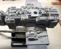
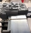
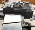
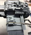
Y-Wing (Gold Leader) Build - Nice-N Model Designs

Corellianexports

Sr Member
RPF PREMIUM MEMBER
I waited a long, long time for Efx (I've already sent them an email, so now they know) to release the SS Y-Wing model via Nice-N Model Designs (I even met Steve at a Celebration with his Y-Wing Prototype) in an attempt to avoid another model project because I'm not anxious to breath in any more spray paint fumes or resin/modeling clay dust, but this is a model that is a personal favorite and one I've always wanted to replace because I had to sell my MR Y-Wing during the great recession to pay a major dental bill.

Of course the good news about building the model is that it can be built just like an original, screen used Y-Wing. The MR version is very nice, but it's solid resin, so it's extremely heavy and the paint job with detailing is a combination of two different versions of the Y-Wing (Gold 3 and Gold 2). Also, the MR version doesn't include an ILM pilot figure. It's true that the screen used Y-Wings didn't have pilots, but I was surprised to find out from Steve that they originally did have pilots before they fell out of the models at some point during filming.

My old MR Y-wing model:

Y-WingCase8.JPG


It looks like their paint scheme came from the ROTJ version of the Y-Wing:
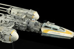
img04.jpg


I poured over lots of reference photos and finally came to the conclusion that I liked the "Gold Leader" version of the Y-Wing the most, so that will be the one I will be building, with a pilot of course. :)

One of the great things about this kit from Nice-N Model Designs is that there is an instruction manual available online, in pdf form. Unfortunately, there are no step by step instructions on painting the model, but there are plenty of resources here on that.

The instructions specify that the first step is to examine and clean all the parts with soap and water. I'm skipping the cleaning part because once all the parts are cleaned up with X-acto knives and sand paper, they just get more dirty. Also, at some point the parts will need to be drilled, cut, bolted, etc.

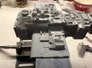
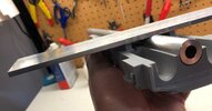
Here's the larger parts partially cleaned up. One of the main sections was slightly angled due to the casting process, so I actually machined it flat although it didn't take much machining:

IMG_1725.JPG

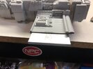
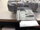
It was easier for me to machined the aluminum bracket rather than cut into the resin parts. This past weekend, I got to the cockpit with canopy and finished cleaning up the engines.
IMG_1726.JPG

IMG_1727.JPG

Detailed Parts with pipping from Plastruct:

IMG_1728.JPG

IMG_1729.JPG

Up next, more stuff from/about Plastruct and (ugh) more clean up.
 
Last edited:
Unfortunately, the kit isn't complete. There are some parts that are needed from Plastruct along with misc. electronics for lighting but more on that later.

The instructions recommend styrene pipping from Plastruct, although vinyl covered wire is also an option, but it's much more expensive. More importantly, "T" track is needed. I checked the local hobby stores and online, but no one carries the lengthy "T" track so I went directly to Plastruct, which is located in City of Industry in SoCal, ironically not far from where I grew up and not too far from where ILM originally built the Y-Wing models.

Here's what I ordered from Plastruct:

Item 90858 (MR-160 / pack of 10) x 1
Item 90861 (MR-125 / pack of 5) x 1
Item 90860 (MR-100 / pack of 5) x 1
Item 900086 (T8 / pack of 4) x 2
 
Hi...i have this kit too and unfortunately some parts are missing and particularly the ring cut on half on the right...Can you give me the sizes of these please ;)...thanks
page11image10617664
 
I bought 3D printed thruster bits from DaveG, the parts were fantastic, much better than the resin supplied parts.
 
Missing Parts2.png

Any one have these parts they can spare?
I know the top one (side lamp?) is from the Tamiya 1/35 8-Rad model kit.
The one near the bottom is from the Bandai 1/48 JagD - Tiger.
 
Last edited:
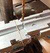
Hi...can u share your y wing instructions please?
You can get them here:

This thread contains lots of great information on SS Y-Wing building, including building instructions, painting, etc:
 
Before I go any further with this build, I wanted to point out that the detailing on this kit is simply amazing. All of the detail parts or "nurnies" have been placed with a precision I'm not sure that I could duplicate and it's probably more precise than the original model. I'm seeing very few bubble holes and lots of straight lines. I've also compared the kit to the original model and I'm simply stunned by the accuracy. It's simply an amazing feat of work. A lot research and leg work went into building the master for the mold and subsequent pulls. It's just too bad that this never went into production. Now, back to the build...

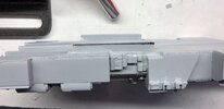
One of the first steps - according to the directions - is to make sure that the large pieces (top, bottom, wings and cockpit) all fit together along with the aluminum "armature" (which is basically just a flat piece of aluminum and a rod) before gluing the two, main pieces together. Last weekend I scratched my head a bit because I noticed that the bottom part was actually longer than the top section. At first, I thought I could adapt or "fudge" the lines together with modelers putty, but after studying the directions and the reference photos, I realized that all of the lines need to be straight.

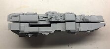
Here's the left side of the top and bottom sections:

IMG_1772.JPG

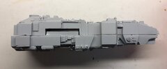
Right side:
IMG_1773.JPG

Notice that the forward section lines up nicely, but the rear/stern area is off by about 1/8".

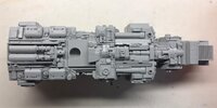
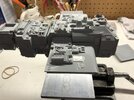
I studied both sections to figure out if one of them could be cut in half without losing any detail. Here's what the bottom part looks like:
IMG_1775.JPG
Not much room to play with here. All of the model kit parts are right next to each other or are staggered like a jigsaw puzzle.
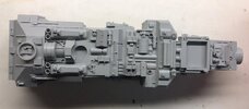
Here's the top half:

IMG_1774.JPG
If you look closely, you'll notice a long, flat surface in the near center, right next to the four cannisters near the bottom of hits photo and the section with the three lines in a pyramid shape. To me, this seems to be the best place to cut the part in half to help adjust the two main sections.
 
Last edited:
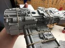
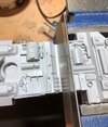
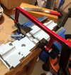
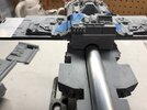
To make sure I don't cut into any of the details, I start with an artists saw and the largest clamp I have:
IMG_1776.JPG

This is probably the largest part of the build and the largest piece of resin I've ever worked on. It's times like these when I think about the amazing work the Egyptian artisans did on objects found in King Tuts tomb. I think about that artwork and suddenly it makes stuff like this seem like child's play; so I just keep on sawing. Then I remember I have another, small saw that should help speed up the process, so I flip the part upside down and start sawing again:

IMG_1777.JPG

Once I get closer to the original cut line, I flip the piece over and continue with the original artists saw, until finally pulling off the front part by hand.

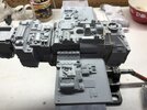
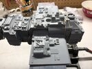
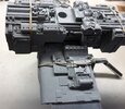
And now for the first time, I've got the major pieces up in the air. If it were an R2, I could say that it was "up on both legs":

IMG_E1778.JPG

And just when I thought it was ready to be glued together and allowed to sit to dry over night......
 
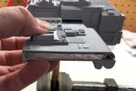
.....I discover more problems. Nothing appears to be lining up correctly. Apparently, I had been scratching my head last weekend over more than just the two main sections not lining up properly. And in order to glue the two main sections together, the wings have to assemble properly and of course, they don't.

So here's the left side wing before attaching it to the main section:
IMG_1779.JPG

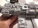
Here it attached:
IMG_1780.JPG
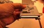
The idea (according to the instructions) is to insert the wing just under the slot, above the aluminum.
Unfortunately, there isn't enough room for the wing and the aluminum. Here's the other side:
IMG_1781.JPG

IMG_1782.JPG

Flipped over, here is the bottom of the right side wing:
IMG_1784.JPG

Bottom of the left side wing:
IMG_1785.JPG

Looking at it from the front, the top section is being pushed up:
IMG_1786.JPG

The reason is that the two, resin wedges are too high:
IMG_1787.JPG

About 1/16" of material needs to be removed on both sides:
IMG_1788.JPG

Sanding them down will take a long time, so I simply machine them down using the mill. There's one problem solved. Next up is the second problem with the wings.
 
Last edited:
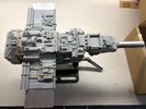
The second problem is that the wing parts are too narrow for the aluminum.

I'm thinking that this is either due to shrinkage or the aluminum is simply too wide:
IMG_1789.JPG

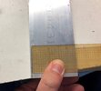
The width is a standard 2 1/2". We need to trim 1/16" off, making it 2 7/16" wide.:
IMG_1790.JPG

Now we're good :D

IMG_1791.JPG

Left side:
IMG_1792.JPG

Right side:
IMG_1793.JPG

Bottom right side:
IMG_1794.JPG

For this part, more material needed to be cut and sanded from the inside of the wing to get it to sit straight against the bottom section.

Bottom Left side:
IMG_1795.JPG
This area proved to be a challenge because part of the wing goes under the detail on the bottom section. I didn't want to remove any of the detail, so I opted for drilling a couple of holes into the bottom section:
IMG_1796.JPG
The area that needed to be drilled was marked with a black sharpie. Interesting enough, the holes needed to be about 1/16" deep.
I used a x-acto knife to create a rectangular area where the two holes were, so the wing detail would fit better:

IMG_1797.JPG

Up next, I finally get to glue the two major parts together......or do I? :unsure:

Which leads me into another question, what is every one using for filling in their seams? Modeler's putty? Apoxie sculpt?
 
Last edited:
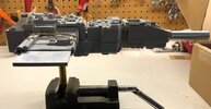
I spent some time studying the references photos today along with the Y-Wing instruction manual and realized my mistake with the wings.
For whatever reason, I had the reversed the top wings with the bottom wings. I think the dual pipes threw me. They seemed to look better on the bottom. :p
So here's the correct set up:
IMG_1819.JPG
Side view:
IMG_1820.JPG

Here's a bottom view:
IMG_1821.JPG

So in reality, the thin part of the bottom wing should fit between the body and the aluminum with a gap. More than likely, a detailed part fills in the gap, but more on that later. Here's a close up of the bottom of the left wing (port):

IMG_1822.JPG

Close up of the bottom of the right wing (starboard). To get a good fitting, about 1/16" worth of material had to be removed from the body, just below the detail:
IMG_1823.JPG

After trimming some material from the inside of the wings, I was able to get the wings to fit closer to the body or fuselage.
 
According to the instructions, once all of the major parts are fitted and the aluminum parts are modified, the hull is glued together and puttied.
Unfortunately, the instructions skip the wiring part, although wire can clearly be seen in the photos.

So at this point, since modifications are already being made to the hull, might as well mark the areas where holes will eventually need to be drilled for the wires that will go to the engines. I used the bottom wing that has a hollow tube already built in as a template for marking the hole.

Top right side:
IMG_1824.JPG

Here's the top left side:
IMG_1826.JPG

After removing still more resin from the top left wing, here it is, fitted:
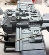
IMG_1828.JPG

Same deal with the top, right wing:
IMG_1829.JPG

Up next, fitting the nose section, modifying the aluminum frame and finally getting those wires installed... :)
 

Your message may be considered spam for the following reasons:

If you wish to reply despite these issues, check the box below before replying.
Be aware that malicious compliance may result in more severe penalties.
Back
Top