Upgrading a resin Bladerunner blaster WIP

Coz

Sr Member
Scored a resin BR blaster kit offa eBay, and decided to go as all-out on it as I can - given that this is my first real resin gun, and I'm a noob. :D

It's a Wilco kit, great detail, REALLY light and a nice quick resin to work with. Not brittle either. I think I'm gonna have to deal with these guys direct, as they have some other cool stuff too. :)

Even though the alan screws and screw heads were almost all blemish free, I decided to replace all of them, and to try and fix some of the inaccuracies.

So I drilled out the heads and ground them down with my Dremel and a milling bit - made a heck of a mess.
Also at this point, I cut off the trigger guard to allow me to add a moving trigger (glutton for punishment.).

Tricky thing was getting the correct size allan bolts - both cap and button head.

After a little thinkin', I decided to add working LEDs too - which is gonna be a pain in the (guess where.). But fun, anyway.

Pics to follow.
 
Pics. :)

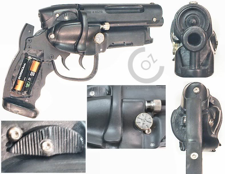
Right Side:
BRPKDStage1J.jpg


Ground off the molded screw head, and replaced it with a faked scope screw (hey, I'm cheap.).
Used a coaxial aerial plug, a bolt and some sculpy. Also mounted it in a drill and filed the off-center line into it (like a poor mans lathe.).
Also made a new adjustment screw with a PC case thumbscrew, a small tube and a washer. This also got mounted in the drill to round off the 'step' before the knurling.

Drilled holes for the magazine holding screws in both sides just for show.
Also reamed out the barrel a little deeper, and added a tube to take it to about the size of a .38. Also filed the angled shoulder at the end of the barrel
Drilled out the backstrap for the hole and screw.

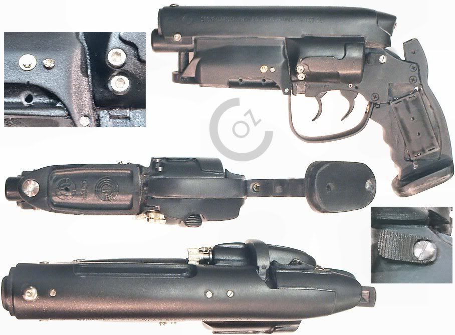
Left Side:
BRPKDStage1bJ.jpg


Cut off and reworked the cylinder release catch to more resemble the Worldcon version. Added the two screw details to the magazine cover.

Also replaced the molded in grubscrews in the steyr bolt section, and added the front button-head allen bolt 'foresight'.

Completely cut out and flattened off the barrel post, as the solid molded one looked bad. Drilled and fitted a replacement and screwed it in with a countersunk allen bolt (since realised this is the wrong size, but it looks neat tho.).

Filed the notch into the backstrap for the hammer (yes, I know it doesn't actually move, but still...)
Extended the buttplate and redrilled more accurate hole placement. Also ground off the screw head in the bottom of the magazine and filled it in.
Drilled and fit a screw in the front of the grip, just under where the trigger guard sits. Also had to add a screw to the trigger guard itself to hold it in place - this will be filled in later to hide it.

As you can see in the pics, I cut a hole in the grip to fit a AAA battery pack - just the right size. Have since begun to feed the wires along the right side of the gun in a long notch under the cylinder cover.

Still need to wourk out the mounting of the switch LEDs in the mag, and add the notched part that should be behind the cylinder, but before the release catch.
Then, a whole bunch of cleaning up, then onto paint.

And then McGivering a suitable holster for it... ;)

Let me know if there's anything I've scrwed up or could do better - as I say, I'm new to resin guns, and need all the help I can get. :D

Thanks fer reading,
Coz.
 
<div class='quotetop'>QUOTE(Coz @ Dec 14 2006, 08:20 PM) [snapback]1378105[/snapback]</div>
Scored a resin BR blaster kit offa eBay, ... I think I'm gonna have to deal with these guys direct, as they have some other cool stuff too. :)


[/b]

Customizing BR blasters is a lot of fun.


EDITED for poorly worded content which could be regarded as negative where negative was not the intention. my apologies.
 
I was unaware of any... problem? Did a search for Wilco on the bard when I won the kit, but nothing about the BR Blaster came up.

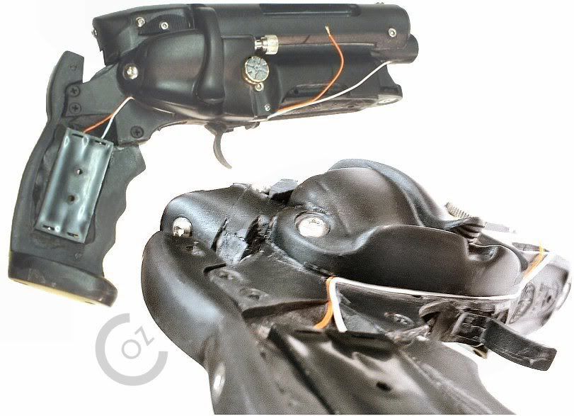
Anyhoo - Got the wiring started:

BRPKDStage1cJ.jpg


Soldered the wires to the battery pack, and dug a channel for them, as I mentioned earlier. Going to fill them in once I've got them all sorted. Had to fit the pack in the other way.
Battery pack is to be epoxied in to give a little more stregth to the grip section (after cutting a big hole in it.).

Oh, forgot to mention - all the screws etc are still removable, as they really are screwed in.

C.
 
This is your first build-up? WOW. You're doing a very nice job. If you've never painted resin before, make sure you read a tutorial or get a little advice. (LITTLE ADVICE: Get Automotive paint and primer. Plasti-kote or Dupli-colour are both good. Make sure you completely WASH all resin parts in soap and water to get any mold release off before priming. Use multiple thin coats of paint. Remember a good clear sealant when you're done.)

Wilco is Alex Wakal, yes? Why would there be any trouble with one of the products Alex sells? Speak up. I have numerous kits he's sculpted and each and every one was of high quality. I recommend him highly.

Jay
 
The thumb screw was ingenious. Coolermax makes one that is almost perfect -even has the bevel - though a phillips screwslot in the top. All these threads make me want to dig my parts out and actually build one up.
 
After rereading my above post, I can see where it placed a negative light on Wilco. My apologies. My dry humor didn't carry well.

I'll edit so that there is no misunderstanding.

I certainly No problem with Wakal at all or Wilco. I own some of them. Just recall some lengthy debates as to who, what, where, and figured this would launch a rebirth of same.

Got PM from Wakal and explained same.
 
That is coming along nicely, can't wait to see it finished. I have a BR SNUB kit on the way, so I'll be in the same boat in a few days. :)
 
Damn, I hate it when people build up Bill and I's stuff better than we do :cry

:lol

Please keep the pictures coming.


Alex
 
Ah, JediRick - thanks for the clarification. Think I might have misconstrued your comment there. apologies.

Thanks for the WOW and the paint tips, Jedi Lawja. (Gee, there's a lot of Jedi on here. ;) ).

jakob2121 - There actually was a phillips screw slot in this one - I just filled it with Sculpy, hit it with a heat gun then sanded it back. Also seeled the sculpey with a dab of superglue, then sanded it again. Once painted the screwslot won't show at all - the perfect crime. :)

Thanks SethB6025. Good luck with the snubby.

Sorry Wakal. ;) I'm just a plodder with a little free time. Great quality cast and resin, BTW. You got a new customer over here. :) Pics will be forthcoming. :D

Thanks, Lord Abaddon. I know what you mean. Sure, it looks great straight outta the box, but you wanna play with it a little first. :)

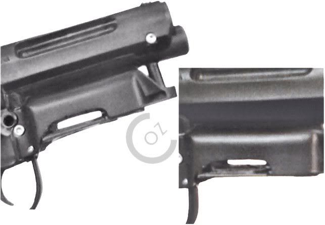
Got a little more done today - poor pics as I only had my phone cam:

BRPKDStage1dtempJ.jpg


Yep, cut a big darn hole through it. Going to set the LEDs in a block to keep everything solid. Hollowed the mag out up to the fifth LED hole underneath, too.

Did a little test, and the two 1.5v AAAs will run seven 3mm LEDs nicely. So today I also drilled out the lasersight / screwdriver thing - so its now hollow.

Fixed the front mounting point of the trigger guard too - the Worldcon pics show a screw in the front of the guard mounting it to the revolver frame just in front of the trigger, so preoblem solved.
Used a heat gun to soften the resin before repositioning it - worked like a dream. Managed to rework the angle a little too.
Also used it to straighten out the lasersighty thing.

Will get better pics after the weekend. :)
 
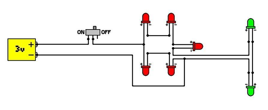
Can anyone tell me if I have this diagram right?

BRLEDWiringJ.jpg


Seven 3mm LEDs, powered by 3 volts from two AAA batteries.

Details according to the assortment box:
3mm green 4.0mcd (Brightness 4)
3mm red 1.0mcd (Brightness 1)

I bodged something together to test that all seven will light, but I need something a little sturdier.

Given that the Green LEDs are brighter, should I add a resistor to the circuit to tone them down a bit? And if so, what rating and where should it be put?

Please bear in mind I'm a little caveman like in regards to electronics. Simpler the better.

Thanks in advance,
Coz.
 
You might want to consider wiring in parallel. That way if an LED fails or a solder breaks you will still have power to the rest of the system.

Here is an example...

wiring.jpg


It's the same way X-mas lights are wired, that way when one burns out the whole string doesn't fail.
 
Just an observation, your trigger guard is a weird shape.. way too big it seems. Could use some cuttin down.

compare to

7215786.jpeg


- k
 
Those are some ridiculously low-light LEDs. Wow. The typical cheapy Radioshack LEDs are 20 mcd.

Based on your diagram, it looks like you've got them running in a series, which means your voltage won't be good enough. They should be wired in parallel with an 82 ohm resistor for the reds and if you want the greens to be even with the reds, a 180 ohm or thereabouts.

You can, of course, hook one 82 ohm resistor to the positive charge and then "octopus" all the positive legs of LEDs to it if you only have the one resistor.

Not using a resistor is bad juju - it overheats the LEDs and will cause them to burn out quicker (when the current isn't enough to make them explode outright).
 
<div class='quotetop'>QUOTE(jakob2121 @ Dec 30 2006, 07:10 PM) [snapback]1387399[/snapback]</div>
You can, of course, hook one 82 ohm resistor to the positive charge and then "octopus" all the positive legs of LEDs to it if you only have the one resistor.[/b]

Although this would work (most of the time) it's generally not a good practice, each LED should have it's own resistor when wired in parallel...

And as stated above running LEDs without limiting resistors (unless there is a controlled current, ie a batteries internal resistance) is only going to drastically shorten the life of the LED, if not turn it into LED popcorn...

This site provides the best (IMO) overall LED "instructions" that I have come across...

http://www.kpsec.freeuk.com/components/led.htm

With a 3volt source you only real option is to do a parallel deal, with LED/resisitor pairs...
 
Yeah, what he said (about running them with one resistor). I was just thinking in terms of limited space.
 
Motive-Alloy, jakob2121, exoray - Thanks for the info on the LEDs. Parrallell it is then. :) Looks like I got me some soldering to do.

phase pistol - Yeah, it does look huge, don't it? :D
In those pics it's only fixed at the grip end - I've now screwed it down at the front which pulls it in quite a bit.
Thanks for making this possible in the first place, BTW.

Cheers all.

C.
 
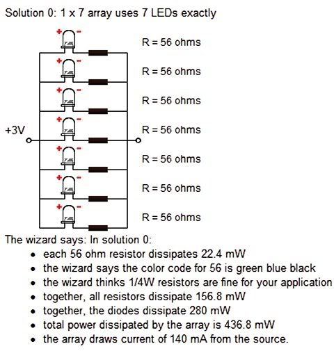
I just found this site which has a calculator for multiple LEDs in parrallel - figured it may be of use to some fellow members projects:

http://led.linear1.org/led.wiz

Also tells you what colour bands you should have on the resistors, and gives you a little wiring diagram too.

Junking the sub-low brightness LEDs I have for some better grade ones (60MCD RED, 40MCD GREEN, so the green won't be as visibly bright), gives me this:

LEDInfoJ.jpg


Now all I gotta do is work on my soldering skills to fit five of them in a roughly 1" square space.

C.

PS - Sorry for all these back-to-back postings.
 
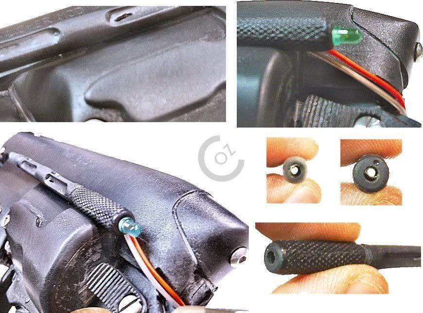
More Pics. And a little bit more done (currently waiting on my LEDs.):

BRPKDStage1dJ.jpg


Test fitting of the lasersighty thing ™. Strightened out real nice. Those are 3mm LEDs, BTW.
Also shots of it drilled out - yep, now it's hollow for the wiring - that was kinda nerve wracking.
Still requires a little cleanup - some small holes appeared during drilling (due to the heat of the drillbit and the resin effectively melting - my fault for rushing.).

BRPKDStage1eJ.jpg


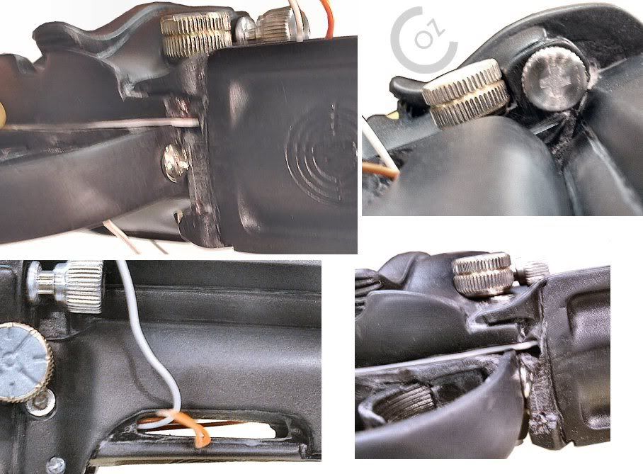
I've now dug a channel for the wiring of green LEDs - these pics show temporary placement of the wires as they run out of the mag, up in front of the cylinder, then across the top, where the laser sits.. They will be glued in and filled over.
Also fed both sets of wires through holes I drilled into where the mag section. Went with one hole on either side - one in, one out. :)

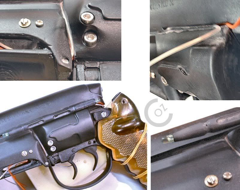
BRPKDStage1fJ.jpg

Couple of pics of the wiring laid in place, and grips rubber-banded on for kicks. Also shows placement of the front trigger guard screw quite well, and the PC thumbscrew with the filled Phillips slot.

To dig the wire channels, I took a fine-toothed jigsaw blade and fitted it to a large exacto type handle (from my razor saw). The saw blade is the perfect width for the wire.

Again, any and all recommendations greatfully received. :D

Later,
C.
 
Back
Top