I don't have much notes on the PCB but I extracted Arky's gerber file long ago for the SMD LED orientation and position. I found one part of the PCB here, which is the front scanner and cleaned it up for you. Anytime you see a small dot on the U-Shape, it is a Negative. I am not sure if you can trust the third image, which is the Lower Interface as I did not do much work on that but created my own version instead.Not quite, the sideways U is actually on the PCB board. I forgot to say that in my original post.
Here is a not so great photo, but a picture is a thousand words! I tried zooming into the image. You can see that where the LEDs (D9, D10, ect) go, there is a U shape, like an open box.
I know that LED's have a negative and a positive, so I am trying to read what is the right way to install them.
You are using an out of date browser. It may not display this or other websites correctly.
You should upgrade or use an alternative browser.
You should upgrade or use an alternative browser.
TR-595E Custom Tricorder
- Thread starter Arky
- Start date
Skyler101
Sr Member
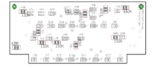
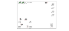
I don't have much notes on the PCB but I extracted Arky's gerber file long ago for the SMD LED orientation and position. I found one part of the PCB here, which is the front scanner and cleaned it up for you. Anytime you see a small dot on the U-Shape, it is a Negative. I am not sure if you can trust the third image, which is the Lower Interface as I did not do much work on that but created my own version instead.
Thank you Mr. Engineer!
I missed the dots on the PCB, but now I know what I am looking for, makes it a whole lot easier moving forward!
Can not wait to get these boards made!
Not quite, the sideways U is actually on the PCB board. I forgot to say that in my original post.
Here is a not so great photo, but a picture is a thousand words! I tried zooming into the image. You can see that where the LEDs (D9, D10, ect) go, there is a U shape, like an open box.
I know that LED's have a negative and a positive, so I am trying to read what is the right way to install them.
Sorry, haven't logged in for a bit! The 'U' shape marks the cathode ( - ).
Oracle
New Member
An appreciation post here to everyone working on this! It's a mildly long one but think you all deserve a pat on the shoulder.
Man been away from the RPF for too long but coming back and finding this thread with all the creativity and cleverness of so many, made me smile.
")
Arky' your unique tricorder design which I love, feels like such a great evolution (love it so much more then the Picard series trics we got!).
Nice work all around from so many here, now can't name all the stuff that impressed me from so many, but JaredTS486, Mr. Engineer, and VincePopcorn: saw photos of all your builds all catch my eye, and they all look like such great work! And seeing others helping with the coding and stuff like wystewart well, the collaboration in this thread reminds me of happier times of days gone by in my youth. How often do you see people collaborating on stuff like this anymore. 'Brings warm feelings ot my heart', to quote an old green guy lol.
Seeing this all got me so inspired and seeing the animations reminded me I need to spend some time getting my own After Effects stuff honestly. So time consuming, but seeing VincePopcorn animations were so cool. I know what those can take to make look right... Last thing I'm still stuck working on for the last year now, has needed about a dozen screens with individual animated gui styles for a crazy Tardis console, so kudos on making those animations look right and work for a tiny screen and still retain the clarity of design too!
Perhaps I can get moving on making something of my own with a working lcd screen... My old Relativity tricorder (not quite the one your all thinking of, its from a different parallel universe) could really shine doing a working lcd screen following these methods you've all utilised here.
Feeling motivated from this wonderful piece of working art you're all working on. Keep up the good work!
Man been away from the RPF for too long but coming back and finding this thread with all the creativity and cleverness of so many, made me smile.
Arky' your unique tricorder design which I love, feels like such a great evolution (love it so much more then the Picard series trics we got!).
Nice work all around from so many here, now can't name all the stuff that impressed me from so many, but JaredTS486, Mr. Engineer, and VincePopcorn: saw photos of all your builds all catch my eye, and they all look like such great work! And seeing others helping with the coding and stuff like wystewart well, the collaboration in this thread reminds me of happier times of days gone by in my youth. How often do you see people collaborating on stuff like this anymore. 'Brings warm feelings ot my heart', to quote an old green guy lol.
Seeing this all got me so inspired and seeing the animations reminded me I need to spend some time getting my own After Effects stuff honestly. So time consuming, but seeing VincePopcorn animations were so cool. I know what those can take to make look right... Last thing I'm still stuck working on for the last year now, has needed about a dozen screens with individual animated gui styles for a crazy Tardis console, so kudos on making those animations look right and work for a tiny screen and still retain the clarity of design too!
Perhaps I can get moving on making something of my own with a working lcd screen... My old Relativity tricorder (not quite the one your all thinking of, its from a different parallel universe) could really shine doing a working lcd screen following these methods you've all utilised here.
Feeling motivated from this wonderful piece of working art you're all working on. Keep up the good work!
An appreciation post here to everyone working on this! It's a mildly long one but think you all deserve a pat on the shoulder.
Man been away from the RPF for too long but coming back and finding this thread with all the creativity and cleverness of so many, made me smile.
Arky' your unique tricorder design which I love, feels like such a great evolution (love it so much more then the Picard series trics we got!).
Nice work all around from so many here, now can't name all the stuff that impressed me from so many, but JaredTS486, Mr. Engineer, and VincePopcorn: saw photos of all your builds all catch my eye, and they all look like such great work! And seeing others helping with the coding and stuff like wystewart well, the collaboration in this thread reminds me of happier times of days gone by in my youth. How often do you see people collaborating on stuff like this anymore. 'Brings warm feelings ot my heart', to quote an old green guy lol.
Seeing this all got me so inspired and seeing the animations reminded me I need to spend some time getting my own After Effects stuff honestly. So time consuming, but seeing VincePopcorn animations were so cool. I know what those can take to make look right... Last thing I'm still stuck working on for the last year now, has needed about a dozen screens with individual animated gui styles for a crazy Tardis console, so kudos on making those animations look right and work for a tiny screen and still retain the clarity of design too!
Perhaps I can get moving on making something of my own with a working lcd screen... My old Relativity tricorder (not quite the one your all thinking of, its from a different parallel universe) could really shine doing a working lcd screen following these methods you've all utilised here.
Feeling motivated from this wonderful piece of working art you're all working on. Keep up the good work!
Thank you! I agree, it makes me really happy to see people taking this project and running with it! You guys have done so much more than I've been able to fumble through by myself, and it's really awesome to see.
I'm so glad this thread is still active, it's such an amazing project. I've once again found motivation to try and complete mine as well. To that end, I was hoping someone could point me to the audio file. I dug up the youtube link, but I don't have a way of downloading it.
Here's the file I used
Attachments
McSrcatchy
New Member
Hey Arky
I've found your data at Github and i am loving it! I'm looking forward to build one for myself. Ordered all parts except the Wireless charging pad.
I'm new to programming also, can you help me out?
So, i've tried Arduino IDE. This way i can compile the Main.ino files and load them up to the pico. Am i doing something wrong until this point?
Afterward the onboard LED is blinking.
BUte i dont know how to connect the pins, do i have to set them up, and in which file do i do this?
I've found a library for the TFT_eSPI (by Bodmer). This is the right one?
1. How do i have to set it up?
2. What do i do with the fonts you added to the Github folder and the lcars.h?
3. What about the Folder 'Project Ressources', what do i do with them?
I'm a little bit lost with all the new stuff.
Also wiring the screen to the Pico is still a mistery to me. Like i said, i added a library fpr the TFT_eSPI, but i dont know how to set it up for the Pico.
And how is the wiring with battery running, do you use a jack or something for it?
Hope you all can help me out here.
Last edited:
McSrcatchy
New Member
Sorry for Doubleposting, but i've got some good News.
After several tries i'll setup my Display using ChatGPT AI, was very helpful. Now the Display is working fine.
I still dont know how to wire the battery with the QI Receiver and the Pico, how does this work? I dont want to kill my pico if i am doing something wrong there.
Where did you put the QI Receiver into? I dont have enough Space to use it.
Does anybody of you have professional printed decals as spare part and would be able to send them to germany? Then dm me please, i am looking for some.
Thank you
Thanks for the reminder. I have updated the post with the Qi Wiring diagram. I have more or less done the decals and I need to look for a local vendor who can print stickers with light blocking features. However, now is close to Chinese New Year esp in Malaysia, and they're too busy to help out with some R&D on this.Sorry for Doubleposting, but i've got some good News.
After several tries i'll setup my Display using ChatGPT AI, was very helpful. Now the Display is working fine.
I still dont know how to wire the battery with the QI Receiver and the Pico, how does this work? I dont want to kill my pico if i am doing something wrong there.
Where did you put the QI Receiver into? I dont have enough Space to use it.
Does anybody of you have professional printed decals as spare part and would be able to send them to germany? Then dm me please, i am looking for some.
Thank you
Skyler101
Sr Member
Hi Guys,
Working through putting together the electronics (this is my first large surface mount project) and wanted to ask, once complete, when you add power to the boards, they should start flashing??
Not to sure if the boards need a clock signal or some sort of data line to get them going. I think it might be human error, so I thought I would ask (doing this all with a soldering iron and might have some loose connections!)
- Skyler101
If you look at the boards, where there is a 555 IC, this component is the one that gives out clock pulses to the bigger 4017 IC chip. So, technically, once you power it up, LEDs would start flashing. The only trouble-shooting clue is that, if the static LEDs are the only ones that lights up, the 555 IC might be suspect or its pin3 to 4017's pin 14 has a issue. But if the LEDs are flashing not in sequence with some LEDs not lighting up when it comes to their 'turn', look at the 4017's soldering.Hi Guys,
Working through putting together the electronics (this is my first large Surface mountproject) and wanted to ask, once complete, when you add prower to the boards, they should start flashing??
Not to sure if the boards need a clock signal or some sort of data line to get them going. I think it might be human error, so I thought I would ask (doing this all with a soldering iron and might have some loose connections!)
- Skyler101
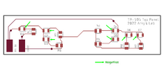
With the exception to the Lower Interface Board (which I have yet to complete), both Top Panel and Front Array board which I re-designed from Arky's, has independent clock generators making them more customisable. That reminds me, I need to upload the latest Top Panel PCB once I can remember how I did that in my own GitHub.
Skyler101
Sr Member
If you look at the boards, where there is a 555 IC, this component is the one that gives out clock pulses to the bigger 4017 IC chip. So, technically, once you power it up, LEDs would start flashing. The only trouble-shooting clue is that, if the static LEDs are the only ones that lights up, the 555 IC might be suspect or its pin3 to 4017's pin 14 has a issue. But if the LEDs are flashing not in sequence with some LEDs not lighting up when it comes to their 'turn', look at the 4017's soldering.
With the exception to the Lower Interface Board (which I have yet to complete), both Top Panel and Front Array board which I re-designed from Arky's, has independent clock generators making them more customisable. That reminds me, I need to upload the latest Top Panel PCB once I can remember how I did that in my own GitHub.
Thanks Mr Engineer!
I had my suspicions that it might be a connection with the 555 chip, but what you described is exactly the issue I have been having. Time to dig in and see if I can save this board!
Thanks again!
-Skyler101
McSrcatchy
New Member
Finally i am DONE!
Tricorder is wired, programmed and closed. Just need to find my screws to finalize it. And have to attach some decals if i can find a cheap nice way to do them.
My last difficult thing is the reedswitch. Killed 3 of them after they were build in, dont know why.
The fouth one is working. But i have to "slam" close the door, otehrwise it wont power off. Any ideas what could be the problem? Without any powersource it works perfect.
Let's look at the the reed switch. I am guessing the one you have is the glass version with two leads on one side and one on the other. These switches are fragile and you would need to grip one of the two leads with pliers before you bend and solder them. Otherwise, the glass will crack and inert gas within will escape. If you solder too long (more than 3 seconds, it might compromise the switch as well, so it is best to tin the leads with flux before performing any touch-soldering.Finally i am DONE!
Tricorder is wired, programmed and closed. Just need to find my screws to finalize it. And have to attach some decals if i can find a cheap nice way to do them.
My last difficult thing is the reedswitch. Killed 3 of them after they were build in, dont know why.
The fouth one is working. But i have to "slam" close the door, otehrwise it wont power off. Any ideas what could be the problem? Without any powersource it works perfect.
Once you got through to that, the switch must be oriented with the magnet's polarity for it to work perfectly when the magnet is energised. Do not secure the switch with epoxy which has metal particles such as JB Weld nor use a hot-melt glue. Plus, the magnets I used are neodymiums.
The reed switches I am using is slightly different and it is the one shown below. It is the NO Type (Normally Open) which is the equivalent to the three lead glass version. I find this version more receptive to the magnet and I can bend the leads without worrying about breaking the switch.
I have re-designed the Top Panel to allow the switch to be soldered onto the PCB instead as I am using this circuit board as power distributor to the other two boards, with a LiPo battery feeding into it. This design also allows you to re-position and test until you get good results with the magnet. Plus, it minimises the need to secure it with epoxy. However, you must know electronics if you want to use this board to mix with Arky's. And yeah, I am a little busy what with the Day Job, launching my Blade Runner Blaster Lighting System and with the Chinese New Year coming up, I have yet to re-look into the latest board before putting it on GitHub.
Lastly, on the curious side, how did you know about the switch working without power? Did you hear the click? The glass ones has a typical switching voltage of 140v while the ones I am using is 100v.
Last edited:
McSrcatchy
New Member
SO, thanks you for you answer. First i'll answer your last question. I used a Multimeter to see if the switch works when detached from a magnetic field.Let's look at the the reed switch. I am guessing the one you have is the glass version with two leads on one side and one on the other. These switches are fragile and you would need to grip one of the two leads with pliers before you bend and solder them. Otherwise, the glass will crack and inert gas within will escape. If you solder too long (more than 3 seconds, it might compromise the switch as well, so it is best to tin the leads with flux before performing any touch-soldering.
Once you got through to that, the switch must be oriented with the magnet's polarity for it to work perfectly when the magnet is energised. Do not secure the switch with epoxy which has metal particles such as JB Weld nor use a hot-melt glue. Plus, the magnets I used are neodymiums.
The reed switches I am using is slightly different and it is the one shown below. It is the NO Type (Normally Open) which is the equivalent to the three lead glass version. I find this version more receptive to the magnet and I can bend the leads without worrying about breaking the switch.
View attachment 1896318
I have re-designed the Top Panel to allow the switch to be soldered onto the PCB instead as I am using this circuit board as power distributor to the other two boards, with a LiPo battery feeding into it. This design also allows you to re-position and test until you get good results with the magnet. Plus, it minimises the need to secure it with epoxy. However, you must know electronics if you want to use this board to mix with Arky's. And yeah, I am a little busy what with the Day Job, launching my Blade Runner Blaster Lighting System and with the Chinese New Year coming up, I have yet to re-look into the latest board before putting it on GitHub.
View attachment 1896319
Lastly, on the curious side, how did you know about the switch working without power? Did you hear the click? The glass ones has a typical switching voltage of 140v while the ones I am using is 100v.
I have some of this switches you use too, but i think they cant handle the voltage oor something. it works for about 5-6 times, afterwards the do not open again to disconnetd the power.
Yes, i use the reed switches made of glass. But i didnt use pliers the first time and i indeed unes hotglue. Now that i have done the switch again, with your advices it seems to wokr pretty well.
McSrcatchy
New Member
Here is the Video of my finished Tricorder. I just used waterslide decals, worked pretty fine.
For the Sound, i didnt get a DFPlayer mini to work, so a worked a bit around of if. Instead, i installed an an Audiomodule where i removed the usb-port an the screws for the speaker. Its just one audiofile with starts immediately after opening.
Dont know if its right that my dispaly needs a second to start showing the intended file. Any ideas how to fix that?
Attachments
Skyler101
Sr Member
Has anyone used different hinges for their Tricorders? I believe that the 80-3050 are no longer being made and only available in the US!
Love to hear some alternatives!
- Skyler101
Similar threads
- Replies
- 2
- Views
- 577
- Replies
- 3
- Views
- 741