Tom’s ROTJ Vader MOM saber!

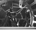
That's the saber I was thinking of - so maybe we're doubling down on proof that there are multiple stunt Graflexes. I forgot that if they both have black bolts... they look alike.
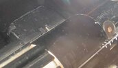
This is the same battle, but I don't see bolts in the same places. In fact, they have different clamps

ESBduel1.jpg
Screen Shot 2019-12-20 at 11.49.38 PM.png


The "pipe" stunt does have a small threaded hole where the red button would be.
SABER_SWR.jpg


I mean, we'd be able to tell a graflex anyway - I believe this to be the MoM Vader saber
BespinDielSilhouette.jpg


but these aren't the same.. right?
Screen Shot 2019-12-20 at 11.48.35 PM.png
DVDbespin006-vi.jpg
stuntsaber1.jpg
fencing2.jpg
 

Attachments

  • bladeref2.jpg
    bladeref2.jpg
    76 KB · Views: 75
I don't think we've got the resolution on these to see any sort of switch/wire holes on these haha.

I'm seeing 3 sabers in these pics

1) Pipe stunt with a red button and without bolts (I don't see any at least)
I forgot that the pipe stunt had the hole for the red button... Either way this pic doesn't match the ANH s-curve to my eyes
1606455116565.png
14.jpg
\
(ANH pic for ref on the curve)
1606455873450.png
1606455890854.png


2)
The long lever stunt - With bolts and without a button. Maybe this is the theorized second ANH stunt? Perhaps the Jawa clamp wound up on this one since the V2 kept its. I doubt there was a reliable source of these levers, otherwise we would've found them by now! But no button does put a damper on that.

1606455061226.png
1606455074492.png
9 eedff7489bda10f5b6052167a7270721.jpg


3) Confirmed ANH stunt used in rehearsal
3b3626f15647614c6ec6a39476fde2a9.jpg


There's plenty of pics of the severed hand stunt.. same with the all the bolted Graflexes...
The only one missing from these ESB pictures is the actual pipe stunt we know today. I can only definitively spot that one in my RotJ pics oddly enough
 
Last edited:
So, heres something to confuse people... the 2nd to last photo against the blue background... theres enough resolution to see the wire hole.. just like the last B&W warehouse shot.

So the red button could come off
 
Ah! I didn't see that. I thought it was a bit of grip coming loose I guess. The warehouse one has the wire hole filled, not sure why they would put weight in one but not the other?

These graflex stunts are confusing, that's for sure
 
Very cool, Tom. I did a first draft of one of these for myself earlier this year, so it's exciting to see your take on it. (My hex screws all have lettering on the heads. Where did you find your blank ones, if you don't mind?)

I'm surprised you're using the top section of the Graflex's innards in your build. Looking at some of the MOM reference photos folks have shared, it looks to me like this one shows the full ring of the Graflex tube without a lip sticking out to interrupt it:

View attachment 838325

This one makes me thing the rectangular hole is filled, and that the circular hole doesn't continue up under the shroud:

View attachment 838326

And in this one I don't think the black plug looks high enough to be on top of the top part of the innards, because it doesn't cover up enough of the far side of the S-curve:

View attachment 838327

It could be I'm misreading these, or you've seen something in the other photos I've missed. I'm curious to know what you think. Thanks!
By the way, Drew you were absolutely right.

2 cores at least, or a milled area around the Graflex socket with fake pins but I doubt that
 
I guess I'm putting it in this thread - does anyone from England have access to M5 or M4 black oxide countersunk allen bolts? I've been using 1/4-20 and having machining issues - can someone measure the head diameter of those? I've looked at some charts from websites but don't know what the cheapest/easiest to get thing is at hardware stores over there, most likely to have been used
 
Alright, I think I've made some headway on this. I'm going to upload my "doodles" and blueprints. I've been having issues because the 1/4-20 bolts I've been using are just too big.

On a curved surface, as you bore a countersink, first the front and back line up flush, leaving "wingtips" on the sides. As you go deeper the sides line up flush and the front and back sink into the surface, leaving the oval bits. Since we're trying to pinch an outer tube to an inner section, and the outer tube is only 1/16" thick, all of that exposed oval area is sacrificed and you're really only using the sides to pinch the pieces together. On a flat surface you use the entire circumference to pinch the pieces together.

In order to get the 1/4-20 bolt heads sunken in... too much circumference has to be sacrificed, so I wondered if the real prop's bolt heads were smaller. This SHOULD leave less exposed oval area and increase the amount of circumference being used.

The real prop has barely any oval area either, I don't know how they did this and pinched the pieces together - can anyone shed light on that? If you bore straight in you're not pinching anything together, just preventing the parts from moving from that position.


uploads to come..
 
20201210_142512.jpg20201210_142526.jpg

First I used some shots to guestimate how big these bolts are, ill upload them from my hard drive in a sec

119472051_743973166162256_1738773665721550566_n.jpgbox2.jpg

I found that the bolts are roughly 1/5 smaller than the graflex sockets, which puts the heads at around 11 mm in diameter. Neat thing is..

Screen Shot 2020-12-10 at 2.39.53 PM.png

Too Small..
Screen Shot 2020-12-10 at 2.39.45 PM.png

Just right!

So I dug up my drafting kit from high school and mapped out these bolts in 1/4-20 size (12.5 mm heads) and M5 size (11.2 max head) inside the hilt/s

Again, if they were these, going straight in, I don't see how the two pieces would clamp together
Screen Shot 2020-12-10 at 2.40.18 PM.png

I found that just going into a countersink with 1/4-20 bolts, until everything is at or below the surface, leaves an oval that is about 18% bigger than the bolt head. I didn't get into technically how much of it was gripping the outer tube... but its about 2 mm on the sides and less than .5 mm on the front and back, the exposed areas
20201210_142541.jpg
With an M5 bolt it would be 13% bigger with 3mm grip on the sides and 1.5mm grip on the front and back in the exposed areas. So better but not perfect.
20201210_142556.jpg

I did notice that this prop itself does not have perfect screws.. i havent mapped them out but some stick up
Screen Shot 2020-12-10 at 2.02.06 PM.pngScreen Shot 2020-12-10 at 2.02.17 PM.pngScreen Shot 2020-12-10 at 2.01.09 PM.png
and some have half an oval.
Screen Shot 2020-12-10 at 2.02.32 PM.pngScreen Shot 2020-12-10 at 2.00.47 PM.pngScreen Shot 2020-12-10 at 2.01.01 PM.png

so definitely not centered, like all mine are, but I'm getting the feeling they did something extra to avoid the oval that I'm not doing?
 

Attachments

  • dvrotjrpfpic1b.jpg
    dvrotjrpfpic1b.jpg
    25.5 KB · Views: 84
Last edited:
This saber is of strange interest to me, so I've been trying to slowly perfect mine for many years. Here are some things I've come to realize:
1. The screws aren't 100% flush. Most are a bit above the surface overall.
2. The reason it isn't uniform is because it was probably done by hand.
3. The purpose of the countersinking was only prevent the screws from interfering wth the actor holding the prop. There were no cosmetic reasons. for it.
4. Don't overthink it! Sometimes it's difficult to see what's right in front of your eyes especially in the case of this prop.
Also, don't forget that the attributes of the base metals make a HUGE difference in how specific drilling tools are effective.
Example: Many moons ago, I made my third ROTJ Vader sabers with stainless steel lamp parts as the base. I used a hand drill. My countersunk screw holes were beautiful TOO beautiful. On my most recent version, I used a vintage Graflex as the base. I used a brand new countersink bit on a brand new drill-press and my countersunk holes were ugly as hell. Weird RIGHT?
Thank you!

My main goal here is to get the core and tube to lock together. 1/4-20 screws bored in dont grip enough of the outer tube. I think M5 ones will... especially if I leave them poking out!
 
This thread is more than 3 years old.

Your message may be considered spam for the following reasons:

  1. This thread hasn't been active in some time. A new post in this thread might not contribute constructively to this discussion after so long.
If you wish to reply despite these issues, check the box below before replying.
Be aware that malicious compliance may result in more severe penalties.
Back
Top