I'm starting a new build of a second and third training remote. I completed one of these years ago and had a lot of fun doing it.
My prior build was in TheRealMcFly 's thread titled Revisiting the Training Remote.

 www.therpf.com
This thread and the other builds there heavily reference BrundelFly 's somewhat definitive tutorial.
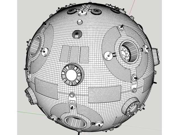
My approach is a little different this time. The parts requiring styrene to be cut out will be replaced by 3D rinted parts. (the large single rectangle, the three rectangles, the semicircles).
I think i'm going to do two builds simultaneously. one will be from original model kit parts and the other will be 3D printed parts.


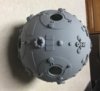
As the first time, starting with Plastruct 6" hemispheres
sanding and marking the 45degree sections and marking where some of the parts will be placed.
I've printed some of the pieces.
The tank parts are all printed and ready but I'm going to revamp the 3 rectangles, single rectangles, semicircles (they're too thin, need to be approx 1.1mm, currently at 0.7mm ish).
The advantage of printing these rather than simply cutting out of styrene is that the remote is curved and they can be printed with the correct curve, which is particularly useful for the semicircles.
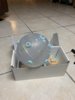
I'm printing on my Elegoo Mars. the parts are printed at 0.025mm layer height, with supports, elegoo resin in various colors.

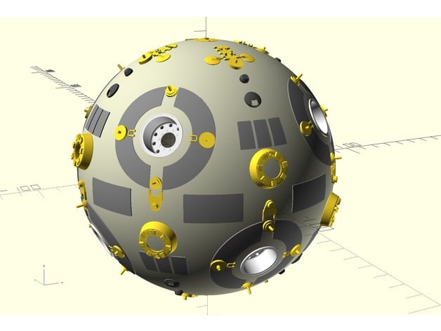
the 3D printed parts come from a couple of different models on thingiverse:
 www.thingiverse.com
 www.thingiverse.com
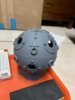
This printer is really great for small details like this. the little U bracket thingy is so tiny but comes out really nice.


this is after removing all of the supports from the prints.

That's all for now. I hope you enjoy.
My prior build was in TheRealMcFly 's thread titled Revisiting the Training Remote.
Revisiting the Training Remote
Hi Niels Thanks for your help! I´ll try to explain me (English is hard to me) In fact, it´s the same question you have done in post #173 I know there is not a big diference, but..... I dont understand some thinks exposed here about diameters, (I want to insert some drawings, but I´m having...
www.therpf.com
This thread and the other builds there heavily reference BrundelFly 's somewhat definitive tutorial.
My approach is a little different this time. The parts requiring styrene to be cut out will be replaced by 3D rinted parts. (the large single rectangle, the three rectangles, the semicircles).
I think i'm going to do two builds simultaneously. one will be from original model kit parts and the other will be 3D printed parts.
As the first time, starting with Plastruct 6" hemispheres
sanding and marking the 45degree sections and marking where some of the parts will be placed.
I've printed some of the pieces.
The tank parts are all printed and ready but I'm going to revamp the 3 rectangles, single rectangles, semicircles (they're too thin, need to be approx 1.1mm, currently at 0.7mm ish).
The advantage of printing these rather than simply cutting out of styrene is that the remote is curved and they can be printed with the correct curve, which is particularly useful for the semicircles.
I'm printing on my Elegoo Mars. the parts are printed at 0.025mm layer height, with supports, elegoo resin in various colors.
the 3D printed parts come from a couple of different models on thingiverse:
Marksman-H combat remote (aka Jedi Training Orb) by profezzorn
3D model of the remote Luke uses for his lightsaber training in Star Wars - A New Hope.Based on pictures of the real thing, modeled in openscad.To make one, print it out, either whole or in parts, paint and weather it.Then either buy some chromed 1:48-scale truck rims to insert, or print out 8...
www.thingiverse.com
Jedi Training Remote by kresty
WORK IN PROGRESS, some of the bits had edges too small to print with the FDM printers I have. I should have them updated maybe by Star Wars Day (May the 4th be with you!)Tons of thanks to profezzom for his Marksman-H combat remote.The goal of these parts are basically to have printable parts...
www.thingiverse.com
This printer is really great for small details like this. the little U bracket thingy is so tiny but comes out really nice.
this is after removing all of the supports from the prints.
That's all for now. I hope you enjoy.
Last edited:


")