Hi folks!
I feel it's been wholy to long since I last made a post here, I've still been working hard on props but mainly in the Facebook space! this project, however, felt like one that needed some extra documentation for future makers Since it's a conversion of a Found part and one that seems to be particularly popular at the moment I thought i'd share my adventure so you can prepare for your own Build
Credit to the Reddit Community as i understand for Correctly Identifying the M42G Alarm Unit this is a now-discontinued (70/80's era) Honeywell-ELAC Military Sounding unit.

Here is how it ends up on the show:

There are several key areas I'd ID'd changed from the original:

1: I belive theese guard rails are not found items although they are common they have several tells that lead me to belive these were created by the prop team
The exposed surface nuts mean the ends of the rod are threaded, this is a very easily done thing in a limited workshop but for a mass produced item this would add needless cost to the product when drilling and tapping a hole in the rod would provide a cleaner and cheaper part, further more there are some tell marks of a non industrial bender being used to form the guards:

these indentations are marks from forming, similarly on a mass produced item these would be die formed and would not feature such "defects", I believe from the shade of metal these are Mild/carbon steel with stock Imperial 10-24 Nuts based on the sizes available & Shim washers
2: After searching for countless hours and likely no less than 5000 switches I'd found the right Switch, this is an NKK Switches "TL22DCAW015C"

3: Included on the original are two D-rings where as in the show we have a formed Top hat loop
4:There are two surface plates on the detonator I believe these are cut from Sheet metal and Epoxy bonded to the surface the damage and weathering lead me to belive they are Mild/Carbon Steel
5:The Side Rails at first i thought were rubber or some cut down plastic part but i belive them to be some model of Picatinny Rail, this may be a red herring as i couldnt find anything to be a dead match based on my modeling of the scaled parts:
 Aluminium showing through Weathering:

I believe they are aluminium mainly because for such a small prop i dont belive they would have spent the time to so expertly topically weather the parts in this way
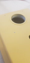
6: The The Bottom edge has been groved out i suspect by a Mill and holes are added, i suspect this is somthing to do with the electronics or perhaps an additional idea the team had for the prop that just didnt work out, i suspect it's somthing to do with power however as they are aligned with the binding posts:

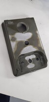
7/8: The BUND Logo and the Sounder Switch have been removed and filled in I also believe the rear model plate was removed, but i'll get to the evidence for that later on!
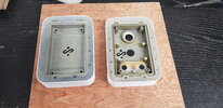
My first step after reciving was to remove the Electronics inside so i could evaluate where I was at I;ve stored all the componants and unused part lest they be some other found part down the line!

The ground point was unscrewed and posts were desoldered from the board, they are mechanically wrapped around the posts so you must use tools to manipulate the parts to remove them if you wish to take them off with care, otherwise, you could snip them off (but you might have issues removing the posts if you do so

at this stage the IP Gasket was also removed and stored, it was only held in by friction and removes with ease.
the Toggle switch was now removed, to remove it requires a Metric Number 14 Wrench, next I desoldered the Peizo Sound unit leaving only the Cluster LED in the center

The Cluster LED was then desoldered and removed with a metric Number 17 Wrench, everything was bagged for safe keeping for the next steps to remove the Peizo unit

after closely inspecting the Peizo unit I discovered the entire unit is Threaded into the Housing, using Card to protect & and a pipe wrench I removed the part with relative ease (I applied some WD 40 to the front threads to ease it along but it was likely ok without this)

There a conformal coating applied to the inside of the casing which would also create issues for moulding as is likely sulfur-based which can be a Cure inhibiting agent. This was cleaned up with wooden tools a Chip brush and some acetone.


be sure to work in a well-ventilated space and wear gloves when working with Acetone.
This is where the learning comes in for folks attempting you require the top half of the Peizio speaker to fit the NKK switch unfortunately for me i have to do this somewhat destructively, the back half of a sharpie was cut down to fit in the hole and use as a hammer punch (with quite some force required)

 the plastics and the piece were entirely destroyed however it revealed to me there was a recessed lip on this part which i may have been able to pry with a wedge, but since this part has to be cut it's no big deal

as you can see the switch doesn't quite fit due to the wide back on the part

using a hacksaw I cut the aluminium threaded section in half which allowed me to excitedly do my first dirt fit of the switch!, take care to clean up the ends of the thread

next up i clamped down the part and begun to go to town on the raised markings using 400 grit with a solid block (to ensure minimal low spots


the Bund logo was braided and scratched up for the next step

to get the lower details flat it was quite tricky i had to resort to a diamond bit dremel to carefully grind of the raised details

any mess here would be dealt with filler later

more wet sanding to smooth things out
 and more ....... next up was filling of the hole & void as I was spanning a wide hole I opted for Metal epoxy

to minimise cleanup i taped the face of the hole and applied from the rear using a stick & toothpick to deair the mix checking the underside periodically, i also masked around the BUND logo to raise the filler and also to clean the edge a little


after 1.5 hours (4-5 hour full cure time) I used a blade to cut the excess (and remove the tape around the BUND to minimise how much i was cutting


after the part was fully cured i wet sanded the area and cleaned with Acetone to remove any dust & residue


I then used £M Spot filler in a couple passes to get the pin holes & Low spots levelled out

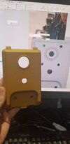
followed by some filler primer to highlight any areas that need further attention

more to follow in the next post!!
I feel it's been wholy to long since I last made a post here, I've still been working hard on props but mainly in the Facebook space! this project, however, felt like one that needed some extra documentation for future makers Since it's a conversion of a Found part and one that seems to be particularly popular at the moment I thought i'd share my adventure so you can prepare for your own Build
Credit to the Reddit Community as i understand for Correctly Identifying the M42G Alarm Unit this is a now-discontinued (70/80's era) Honeywell-ELAC Military Sounding unit.
Here is how it ends up on the show:
There are several key areas I'd ID'd changed from the original:
1: I belive theese guard rails are not found items although they are common they have several tells that lead me to belive these were created by the prop team
The exposed surface nuts mean the ends of the rod are threaded, this is a very easily done thing in a limited workshop but for a mass produced item this would add needless cost to the product when drilling and tapping a hole in the rod would provide a cleaner and cheaper part, further more there are some tell marks of a non industrial bender being used to form the guards:
these indentations are marks from forming, similarly on a mass produced item these would be die formed and would not feature such "defects", I believe from the shade of metal these are Mild/carbon steel with stock Imperial 10-24 Nuts based on the sizes available & Shim washers
2: After searching for countless hours and likely no less than 5000 switches I'd found the right Switch, this is an NKK Switches "TL22DCAW015C"
3: Included on the original are two D-rings where as in the show we have a formed Top hat loop
4:There are two surface plates on the detonator I believe these are cut from Sheet metal and Epoxy bonded to the surface the damage and weathering lead me to belive they are Mild/Carbon Steel
5:The Side Rails at first i thought were rubber or some cut down plastic part but i belive them to be some model of Picatinny Rail, this may be a red herring as i couldnt find anything to be a dead match based on my modeling of the scaled parts:
I believe they are aluminium mainly because for such a small prop i dont belive they would have spent the time to so expertly topically weather the parts in this way
6: The The Bottom edge has been groved out i suspect by a Mill and holes are added, i suspect this is somthing to do with the electronics or perhaps an additional idea the team had for the prop that just didnt work out, i suspect it's somthing to do with power however as they are aligned with the binding posts:
7/8: The BUND Logo and the Sounder Switch have been removed and filled in I also believe the rear model plate was removed, but i'll get to the evidence for that later on!
My first step after reciving was to remove the Electronics inside so i could evaluate where I was at I;ve stored all the componants and unused part lest they be some other found part down the line!
The ground point was unscrewed and posts were desoldered from the board, they are mechanically wrapped around the posts so you must use tools to manipulate the parts to remove them if you wish to take them off with care, otherwise, you could snip them off (but you might have issues removing the posts if you do so
at this stage the IP Gasket was also removed and stored, it was only held in by friction and removes with ease.
the Toggle switch was now removed, to remove it requires a Metric Number 14 Wrench, next I desoldered the Peizo Sound unit leaving only the Cluster LED in the center
The Cluster LED was then desoldered and removed with a metric Number 17 Wrench, everything was bagged for safe keeping for the next steps to remove the Peizo unit
after closely inspecting the Peizo unit I discovered the entire unit is Threaded into the Housing, using Card to protect & and a pipe wrench I removed the part with relative ease (I applied some WD 40 to the front threads to ease it along but it was likely ok without this)
There a conformal coating applied to the inside of the casing which would also create issues for moulding as is likely sulfur-based which can be a Cure inhibiting agent. This was cleaned up with wooden tools a Chip brush and some acetone.
be sure to work in a well-ventilated space and wear gloves when working with Acetone.
This is where the learning comes in for folks attempting you require the top half of the Peizio speaker to fit the NKK switch unfortunately for me i have to do this somewhat destructively, the back half of a sharpie was cut down to fit in the hole and use as a hammer punch (with quite some force required)
as you can see the switch doesn't quite fit due to the wide back on the part
using a hacksaw I cut the aluminium threaded section in half which allowed me to excitedly do my first dirt fit of the switch!, take care to clean up the ends of the thread
next up i clamped down the part and begun to go to town on the raised markings using 400 grit with a solid block (to ensure minimal low spots
the Bund logo was braided and scratched up for the next step
to get the lower details flat it was quite tricky i had to resort to a diamond bit dremel to carefully grind of the raised details
any mess here would be dealt with filler later
more wet sanding to smooth things out
to minimise cleanup i taped the face of the hole and applied from the rear using a stick & toothpick to deair the mix checking the underside periodically, i also masked around the BUND logo to raise the filler and also to clean the edge a little
after 1.5 hours (4-5 hour full cure time) I used a blade to cut the excess (and remove the tape around the BUND to minimise how much i was cutting
after the part was fully cured i wet sanded the area and cleaned with Acetone to remove any dust & residue
I then used £M Spot filler in a couple passes to get the pin holes & Low spots levelled out
followed by some filler primer to highlight any areas that need further attention
more to follow in the next post!!