You are using an out of date browser. It may not display this or other websites correctly.
You should upgrade or use an alternative browser.
You should upgrade or use an alternative browser.
T-47 Snowspeeder 1:1 full scale prop build
- Thread starter TXarmory
- Start date
I hadn't seen this "Making of ESB" before. Lots of great Snowspeeder ref images
https://www.youtube.com/watch?v=5sdB4zedK4w
https://www.youtube.com/watch?v=5sdB4zedK4w
Looks amazing! Is that your Long-EZ?
The plane is for sale if anyone is interested. It's a Velocity 4 seat.
FYI - on the full scale build, the designers added a tiny support rod under the two barrels to keep them from sagging. See link:
COOL PHOTO!
http://ladymanson.com/galleries/movies/MoviesRS/displayimage.php?pid=105408&fullsize=1
Sagging shouldn't be a problem. These are 1/8" thick sidewall, 4" diameter heavy duty aluminum pipe, supported through 4 bulk heads. I dare say that a small kid could sit on the end and it wouldn't bend. Thanks for posting the pic.
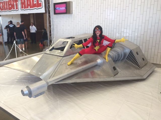
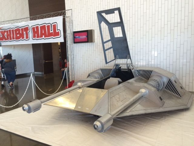
Jumping ahead in time and out of chronological story telling order, if your reading this thread sequentially, but we displayed the T-47 for the first time at the Dallas Fan Days / ComicCon this weekend, Oct 17-18. I wanted to post some of the pictures while it was fresh on my mind. The interior wasn't done yet so we didn't allow people to sit inside it, but I did let a few sit on the wing pods. Now back to the chronological build order....

We are at the Tulsa Wizard World this weekend, Oct 23 - 25 with the Landspeeder. You Okies come see us.
Halloween weekend we will be in Austin at Wizard World, again with the Landspeeder.
I'll catch up on the last 10 days of construction on the T-47 when I get back. Right now it's disassembled sitting in the corner of the shop while we make some upgrades to the X-34 Landspeeder in preparation for the show. This has to be really confusing to some of you who are readying this thread in real time, as I post it.
Last edited:
WOW! Outstanding! ")
Tuesday October 6, 2015. Day 52 of the build.
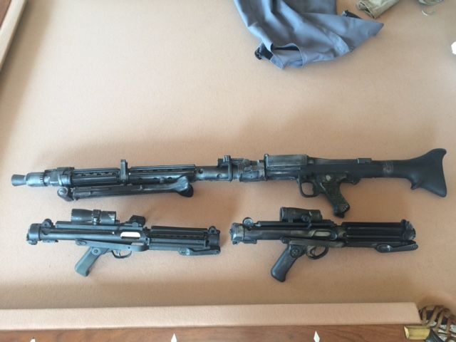
Some new toys arrived today by FedEx. I've been wanting to buy a DLT-19 for 20 years since I built my first Stormtrooper armor in 1995. I finally found a hyperfirm model and picked up an E-11 hyperfirm ( one on the right ) at the same time. It's not nearly as sharply detailed as my good resin E-11 ( on the left ), but it won't break if I drop it. Both will be used extensively when we display the X-34 Landspeeder at cons.
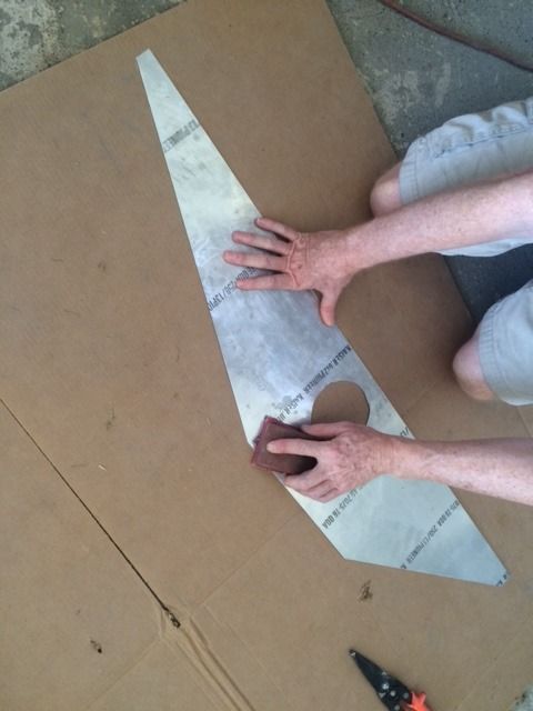
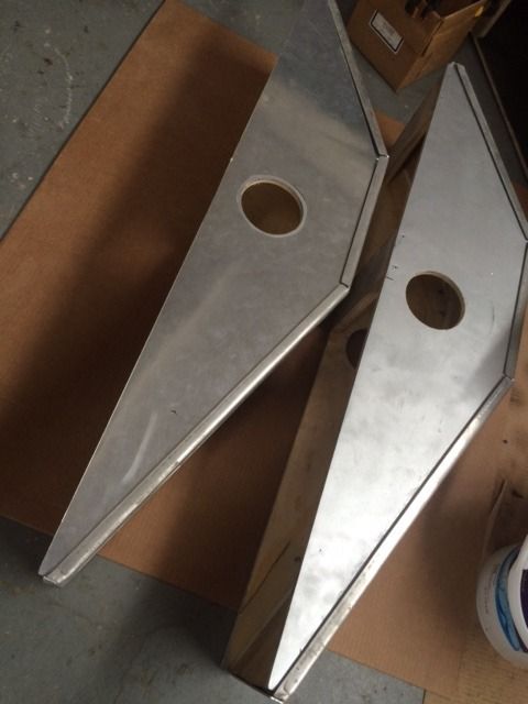
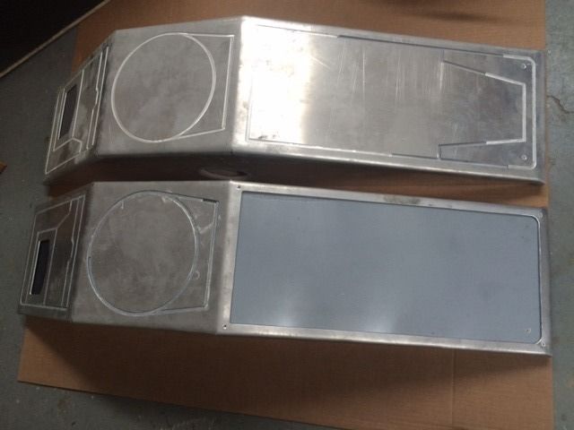
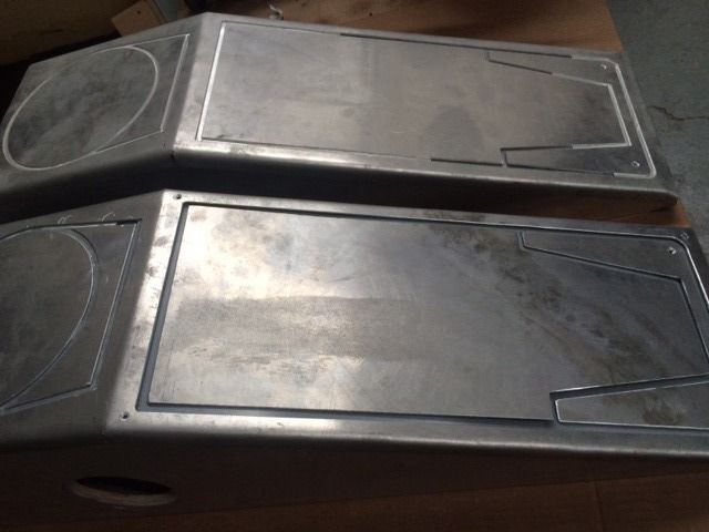
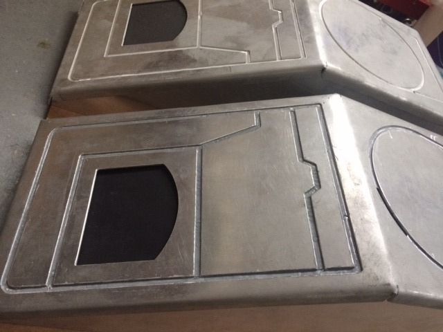
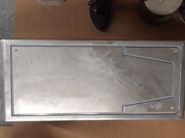
The front and rear vertical faces of the gun and engine boxes had been Krylon Aluminum painted sanded plywood. It looked OK, and even had a nice reflectivity in the right light, but the goal is to have a completely aluminum Snowspeeder. So we are covering those 8 faces with .030" thick aluminum sheet. The first panel we trimmed by hand to make sure we had a good pattern. The remaining panels we cut on the sheer table.
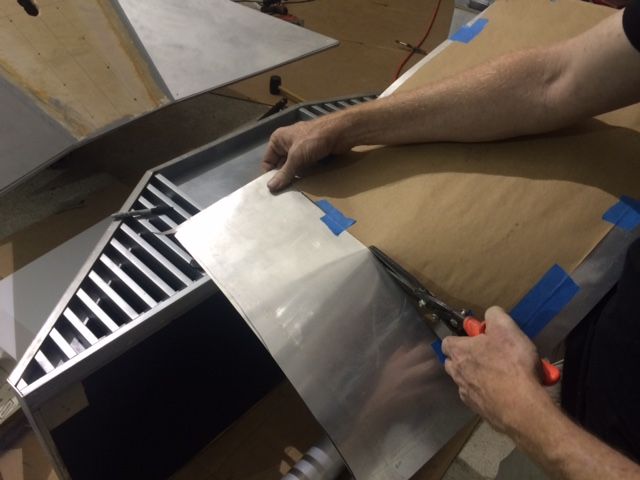


To cut the round hole so the gun barrel could slide through we ganged all 4 pieces together and cut the circles out with the nibbler cutter.

We acetone cleaned and sanded the back sides of each piece to prep it for the urethane glue.
Urethane glue and weights left in place overnight to ensure the panels adhere flat to the subsurface.
Some new toys arrived today by FedEx. I've been wanting to buy a DLT-19 for 20 years since I built my first Stormtrooper armor in 1995. I finally found a hyperfirm model and picked up an E-11 hyperfirm ( one on the right ) at the same time. It's not nearly as sharply detailed as my good resin E-11 ( on the left ), but it won't break if I drop it. Both will be used extensively when we display the X-34 Landspeeder at cons.

The front and rear vertical faces of the gun and engine boxes had been Krylon Aluminum painted sanded plywood. It looked OK, and even had a nice reflectivity in the right light, but the goal is to have a completely aluminum Snowspeeder. So we are covering those 8 faces with .030" thick aluminum sheet. The first panel we trimmed by hand to make sure we had a good pattern. The remaining panels we cut on the sheer table.


To cut the round hole so the gun barrel could slide through we ganged all 4 pieces together and cut the circles out with the nibbler cutter.

We acetone cleaned and sanded the back sides of each piece to prep it for the urethane glue.

Urethane glue and weights left in place overnight to ensure the panels adhere flat to the subsurface.

Last edited:
Ok TX... maybe I missed something. Are you telling us you're NOT going to paint this to look like a real Snowspeeder and are just gonna leave it metal looking like one of those god awful chrome edition vehicles that AMT came out with? Please tell me it isn't so!!
For now we will leave the exterior armor panels the unpainted matte aluminum. Once we get the red stripes and the artwork painted in place we'll re-evaluate the overall body color option. The raw aluminum just speaks so loudly that this is a authentic, solid, military grade piece of combat hardware. I guess I'm just used to seeing exposed riveted aluminum airplane fuselages, so it looks very natural to my eye. I am not polishing any of the aluminum, in fact I have toned down and scuffed up some of the panels to give it more weathering. More will come with the first round of detail painting.
Wednesday, Oct 7. Day 53.
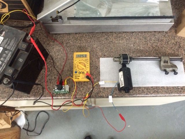
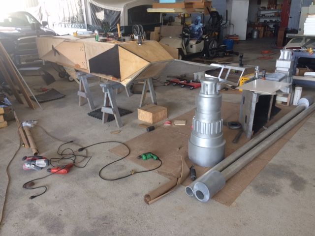
While I am waiting for the laser cutting shop to finish with the remaining armor panels, I start exploring some of the electronics that I've been collecting. The lifting function of the canopy will be automated with dual ball screw actuators. 12 volt drive systems and end of travel limit micro switches. Testing shows that they move 8" in 6 seconds, and pull about 1.5 amps unloaded and around 6 amps with me leaning on them pretty hard to simulate a working load. The plan is for most of the 26 pound weight of the 5-1/2 foot long canopy, will be supported by a pair of gas shock lifting tubes attached to the hinges.
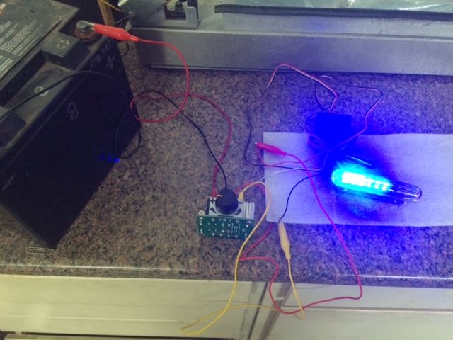
The interior dash and cockpit controls are going to need some eye catching electronic lighting effects. I've sourced a number of different styles and colors of sweeping LED light boards and some rotating LED flasher boards, that when put in combination should give some cool diffused panel lighting effects behind some of the key instrumentation panels.
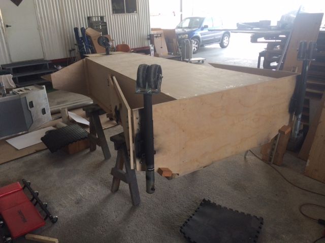
We flipped the cockpit tub upside down and placed in on saw horses so we could address some of the bottom items.
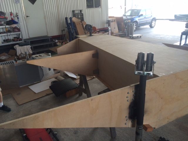
You can see how the wing supports fold in on each other to reduce the width for trailering and going through narrow doors.
When standing more than 20 feet away from the front of the speeder, the front nose area had too much of a protruding chin underneath. We originally thought we needed this extended flat area for leg room, but once we got further along with the cockpit seating position, we decided we did not need the extra toe room and would rather not see so much bulk under the front of the speeder.
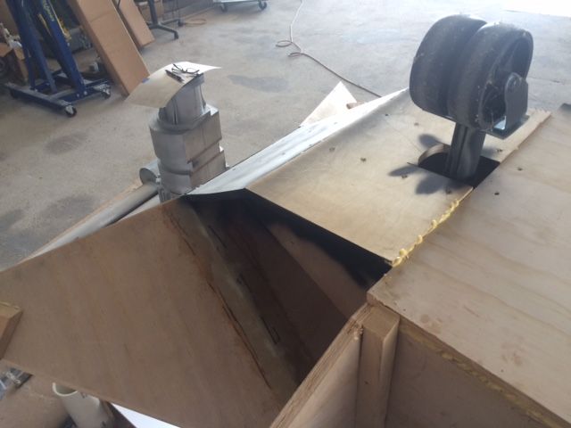
We removed the two panels, to expose the support ribs for the nose. You can see the two cut outs where the pilot sticks his feet through the front bulkhead. We expanded the height of these cutouts to give a little more shin room for tall pilots. We will wrap this in padding to protect their shins.
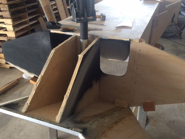
We drew a direct line from the edge of the nose to the floor of the main cockpit tub, and cut the two support ribs to now accept a newly cut single floor piece. This is now a one piece flat chin that is much less visible when looking at the front of the speeder. We also cut two triangular vertical side pieces to close off the foot-well. Before this, the outsides of the foot-wells were open to the air, and if you got low enough you could see into the cockpit floor. Now it is all sealed off and painted black inside.
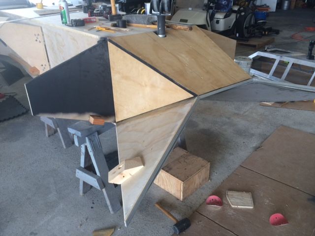
A different angle showing the finished enclosed chin. The perspective from the camera makes the two center rows of screws look non-parallel. But they are parallel on each side of the front landing gear wheels.
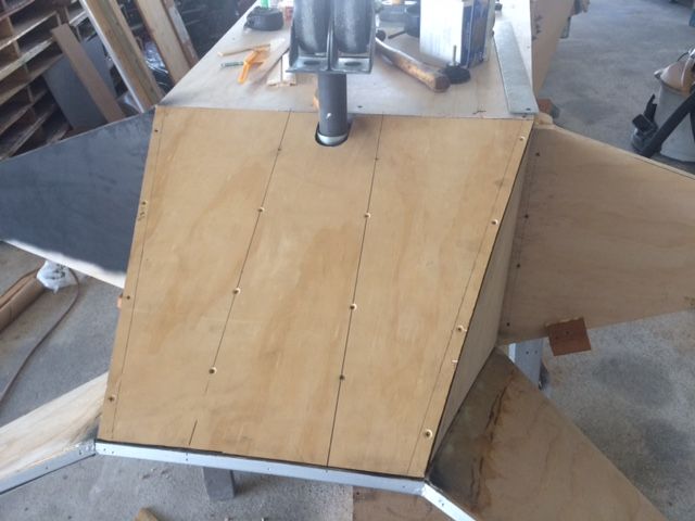
If the aluminum armor panels get cut, and I bend them correctly as planned, then the center nose armor will wrap around the leading edge of 3/4" wood and continuously cover this chin panel in a single armor plate. You'd have to get down on the floor to see it, but it will look very aerodynamic if anyone does.
While I am waiting for the laser cutting shop to finish with the remaining armor panels, I start exploring some of the electronics that I've been collecting. The lifting function of the canopy will be automated with dual ball screw actuators. 12 volt drive systems and end of travel limit micro switches. Testing shows that they move 8" in 6 seconds, and pull about 1.5 amps unloaded and around 6 amps with me leaning on them pretty hard to simulate a working load. The plan is for most of the 26 pound weight of the 5-1/2 foot long canopy, will be supported by a pair of gas shock lifting tubes attached to the hinges.

The interior dash and cockpit controls are going to need some eye catching electronic lighting effects. I've sourced a number of different styles and colors of sweeping LED light boards and some rotating LED flasher boards, that when put in combination should give some cool diffused panel lighting effects behind some of the key instrumentation panels.

We flipped the cockpit tub upside down and placed in on saw horses so we could address some of the bottom items.

You can see how the wing supports fold in on each other to reduce the width for trailering and going through narrow doors.

When standing more than 20 feet away from the front of the speeder, the front nose area had too much of a protruding chin underneath. We originally thought we needed this extended flat area for leg room, but once we got further along with the cockpit seating position, we decided we did not need the extra toe room and would rather not see so much bulk under the front of the speeder.

We removed the two panels, to expose the support ribs for the nose. You can see the two cut outs where the pilot sticks his feet through the front bulkhead. We expanded the height of these cutouts to give a little more shin room for tall pilots. We will wrap this in padding to protect their shins.

We drew a direct line from the edge of the nose to the floor of the main cockpit tub, and cut the two support ribs to now accept a newly cut single floor piece. This is now a one piece flat chin that is much less visible when looking at the front of the speeder. We also cut two triangular vertical side pieces to close off the foot-well. Before this, the outsides of the foot-wells were open to the air, and if you got low enough you could see into the cockpit floor. Now it is all sealed off and painted black inside.

A different angle showing the finished enclosed chin. The perspective from the camera makes the two center rows of screws look non-parallel. But they are parallel on each side of the front landing gear wheels.

If the aluminum armor panels get cut, and I bend them correctly as planned, then the center nose armor will wrap around the leading edge of 3/4" wood and continuously cover this chin panel in a single armor plate. You'd have to get down on the floor to see it, but it will look very aerodynamic if anyone does.

Last edited:
JJ Griffin
Sr Member
Saw this thing at Dallas Comic Con last month and wish I had been able to get a pic of it in my Finn costume! Great job!
Thursday Oct. 8. Day 54.
Before we removed the wings and flipped the center tub upside down, we experimented with how we expected people to be able to climb in and out of the cockpit safely and without hurting themselves or the speeder. After a few uncomfortable tries stepping down into the cockpit from a standing position on the wing, we determined that even with some form of removable scaffolding handhold to hang onto, it is just too far of a distance down to the floor of the cockpit to be able to step down to. After a few more different, but unsuccessful styles of climbing and crab-walking up the wing and crouching low before stepping into the cockpit, we hit upon a successful and what we think will ultimately be a much safer technique.
Placing one foot on the wing about 6" up from the edge of the wing, you step up and pivot your body and sit down on the flat horizontal top of the gun box. From this sitting position you swing both legs up and over the gun barrel. Then slide your butt over a few more inches closer to the cockpit edge. Then swing both legs down into the cockpit until you are standing on the seat cushion. From there, you stand upright facing forward and lower yourself down into a seated position. Reverse the procedure to exit. When we get the body put back together I will take a series of pictures to demonstrate the text.
I tell you all this now, because what we found during all of that playing on the speeder, was that the laser cut edges of the aluminum armor plating on the gun boxes was very sharp and would tear clothing and potentially cut skin. The next set of armor was not ready for pickup from the laser cutter, so I took the time tonight to remedy this future problem. We disassembled the gun boxes and filed and sanded all of the edges to a nice smooth edge radius. No sharp edges or pointy spots to snag upon. We also added a few more coats of the grey paint that shows between the armor plates. Think grout lines on tile floors.

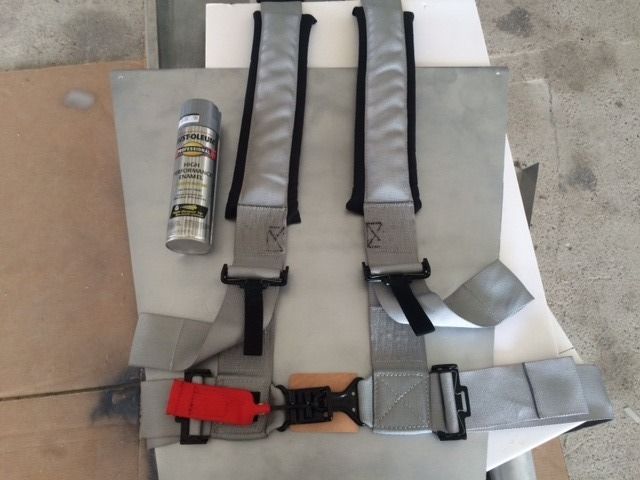
The seat belt arrived today. It had some large tags sewn onto the straps that had warning messages and the manufactures logo, so we spent a while with a stitch puller ripping threads and removing everything that needed to go. It is a massive 3" wide, 4 point harness with military style, quick disconnect at the lap. The black padding is just about perfect for the screen accurate shoulder harness. We will probably strip the black paint off of the connecting hardware, as I think the screen used harness had bare aluminum hardware. Still need to do a little more research. Paint can for scale reference.

Last edited:
Excellent! Dont forget the bubble wrap material the designers used located at the shoulders
Similar threads
- Replies
- 25
- Views
- 1,073