T-47 Snowspeeder 1:1 full scale prop build

Thursday, April 30. Day 27 of build.

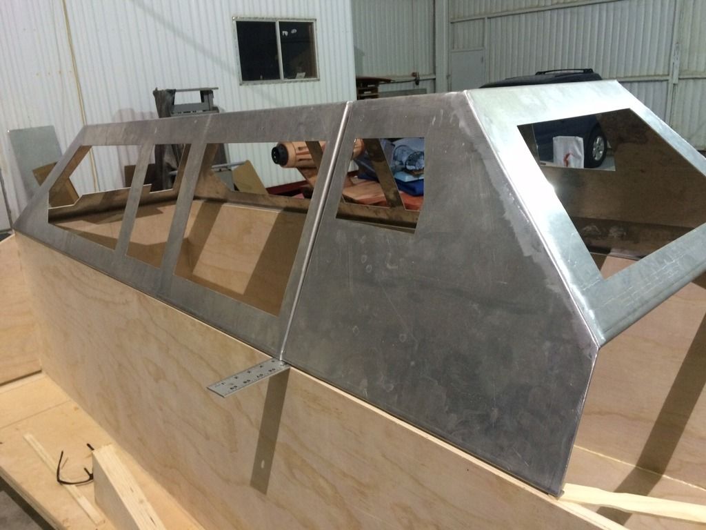
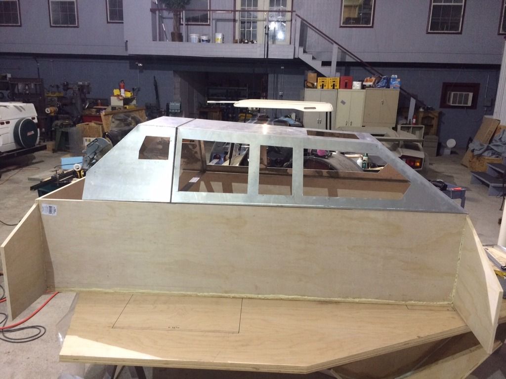
Rear canopy sitting in place.


Inside view looking through rear window.


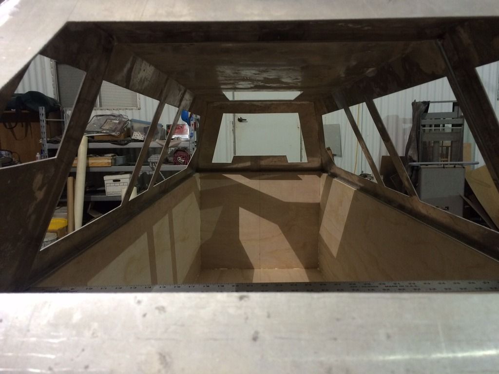
We reinforced all of the glued joints, at every right angle, with a 1-1/2" x 1-1/2" pine board that is through screwed with 2" long deck screws about every 8" to 12". Making the main tub very rigid.


The "landing gear" for the speeder is a three point set of 1000 pound, dual wheel, trailer lift screw jacks. Each set is through bolted with 4, 3/8" bolts. One wheel jack in the front.


Two at the rear.


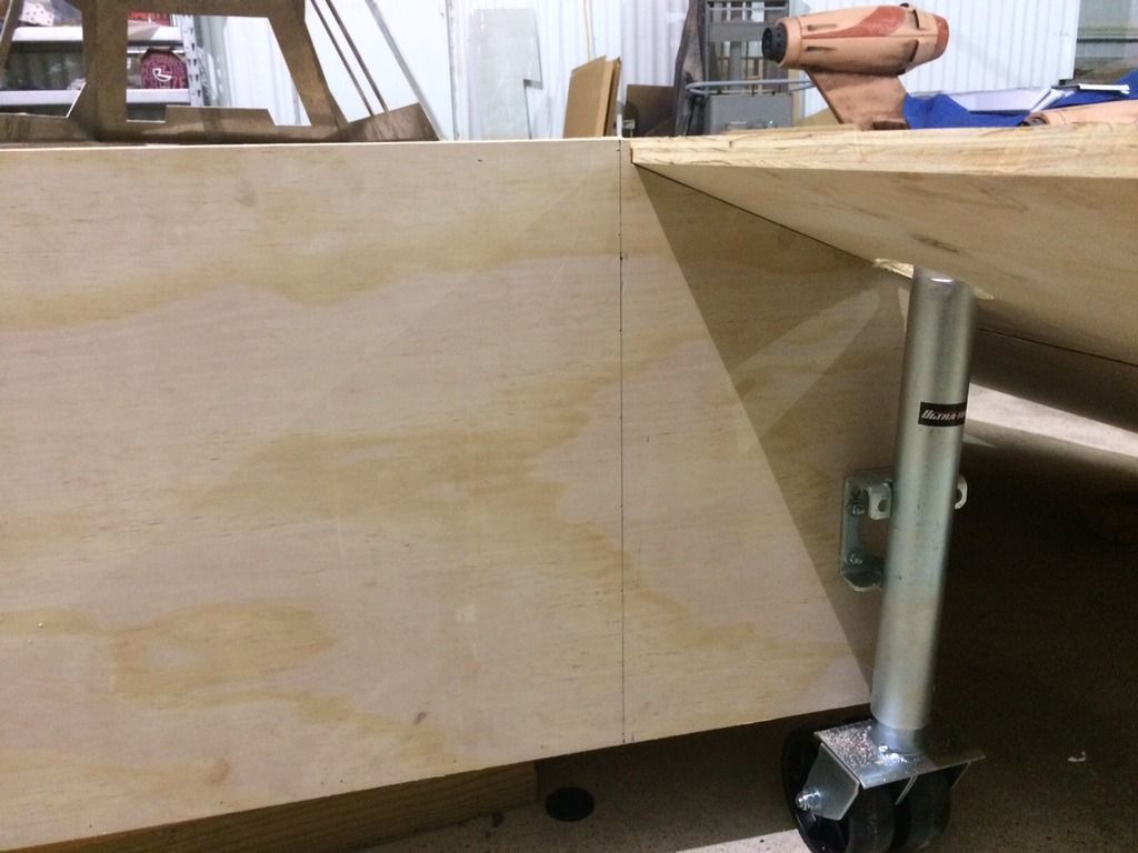
The original turn handle would be in the way of the body panels, so we cut off each original arm and replaced the arm with a 5/8" nut welded onto the short stub. We will use a 5/8" ratchet drive when we need to raise and lower the speeder. Pushing the speeder on and off the trailer, and up ramps at convention halls, might require us to raise the speeder up 5" to 10" above its 6" designed ground clearance height while on display.


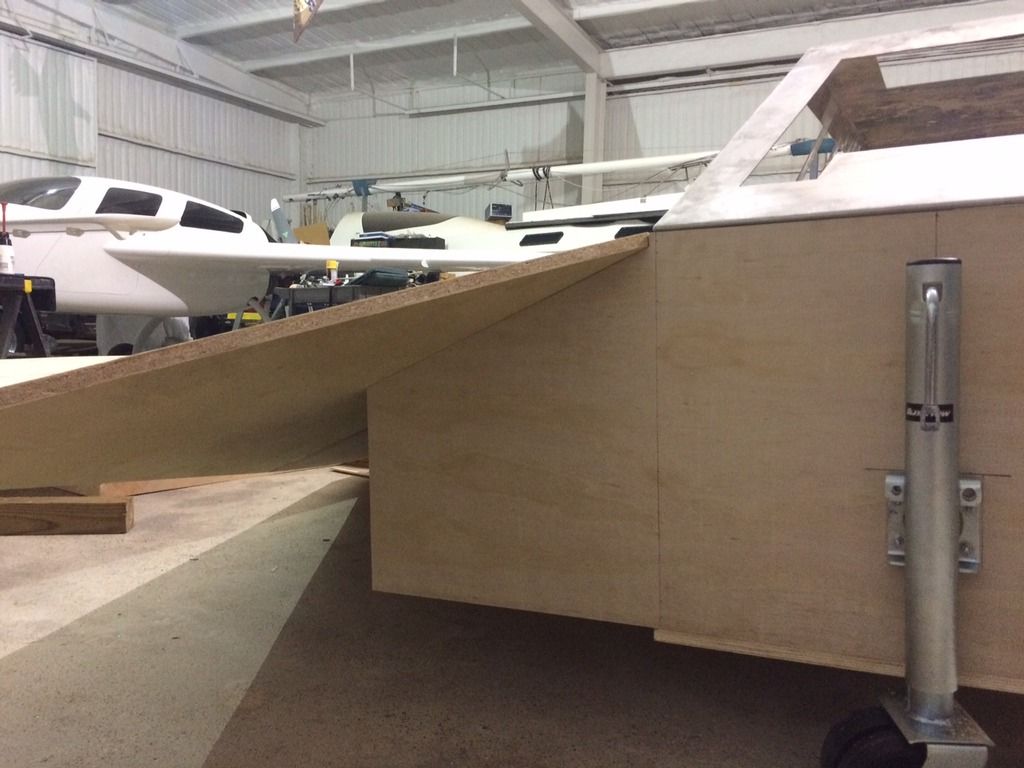
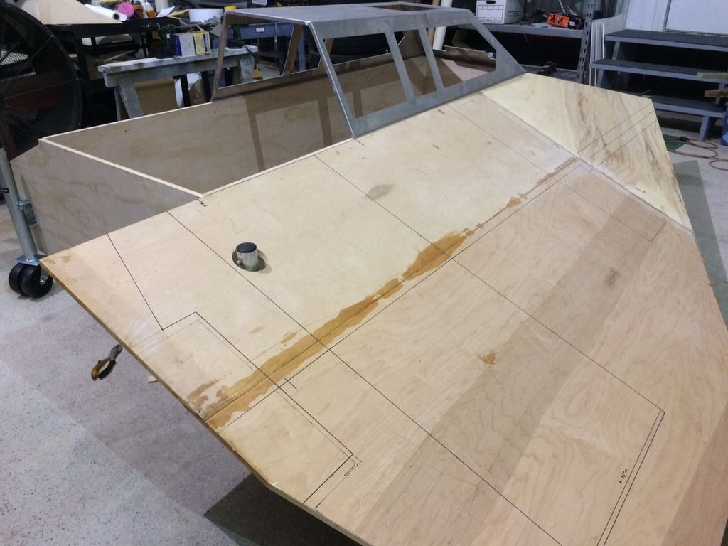
The starboard wing panel is propped up on blocks and sitting in place. We cut a 4" hole in the wing to allow the top of the wheel jack to pass through the wing. This will be hidden inside of the rear engine box. The 5/8" nut will be accessed through a small peephole in the back wall of the engine box.


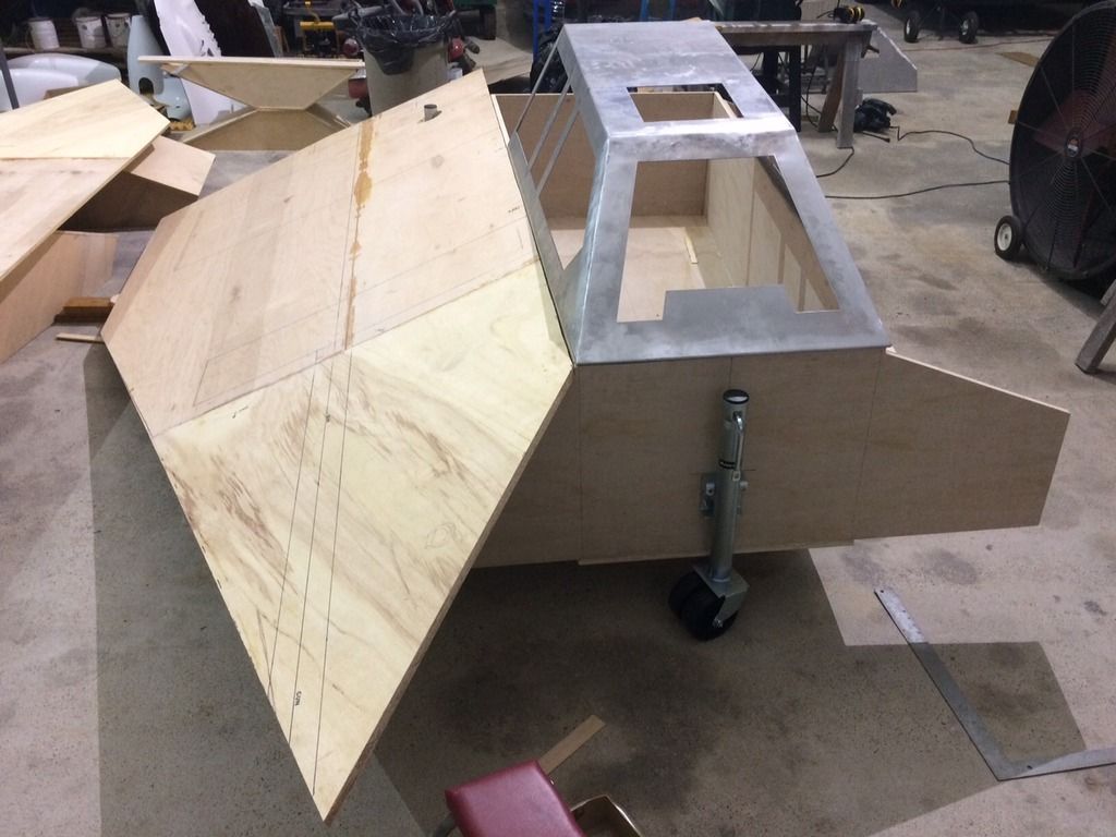
We still have not cut the rear flap of the wing panel. The solid edge keeps it stronger when we move it.


Last edited:
Friday. May 1, 2015

On the 3 axis CNC router we cut some of the wrap around detail parts for the two cannon sections. 1" thick expanded PVC plastic makes a nice chip on the router.


These will be 7" wide by 28" long by 1" high details for the cannon section.


The heat gun applies enough focused heat to bend a couple of inches at a time.


Held in place with the ratchet straps while the urethane glue dries.

 
Saturday, May 2.

Collecting a big pile of cut off 3/4" plywood.


The front pilot seat doesn't leave a lot of leg room from the the front dash and canopy window. To maximize the structural rigidity and torsional stiffness, we made the front and rear main bulkheads full width single sections that cap off each end of the cockpit tub. To give the pilot some leg room requires that we cut 8" wide leg holes so the pilot's legs extend into the front nose portion of the speeder tub. This will keep the proportions and scale right and make the speeder sturdy. The 4" hole saw has been handy for quite a few holes so far.


It is now time to start bending and hand fitting some of the 1/10" thick aluminum armor plating. On the 3 axis CNC router we cut out the armor skins that will cover the two front gun boxes. We cut a 50% depth cut with the 1/4" wide router bit, all of the detail lines on the flat panel. The armor panels will all be installed with a 1/4" gap between panels. On these small gun box armor plates, I didn't want so many small individual pieces so we faked the 1/4" gap by cutting these shadow gaps in the metal. The aluminum didn't lay as flat as I expected on the vacuum table, so the router cut all the way through in some areas. We'll increase the vacuum pressure on the other panels to force them to lay flatter.


I first bent the 90 degree edge bends that create a 3/4" edge lip on all four sides.


A box brake (bender) allows an infinite combination of teeth to be removed and repositioned side by side so that you can fold inside corners. The limit is just the 48" overall width. With a little creative positioning you can make complete 4 sided sheet metal boxes. These aluminum panels are 50-1/2" long so I first had to bend the ends to get the rest of the panel to barely fit into the 48" wide jaws.


Both gun boxes edge bent and angle bent to fit the wood frames.

 
Last edited:
Sunday afternoon, May 3, 2015. Day 30. 1 month of constant nights and weekends. My family thinks aliens must have abducted me.

Establishing the seat back angle for the pilot's seat. This full width panel also stiffens the center of the cockpit tub so that the wing support panels can be added.


We learned with the Landspeeder that sometimes we have to be able to fit it through double wide doors that are barely 6' wide. So when designing the substructure of the Snowspeeder we are keeping it no wider than 5-1/2 feet wide. The wing panel supports will fold inward against the tub body and stay under the 70" wide maximum width target. Heavy duty stainless steel hinges are through bolted with 1/4" bolts. When the wing supports are extended in place to hold up the wing panels, the load is transmitted through the edge ends of the 3/4" wide plywood, back into the full width 3/4" bulkhead panels. This will make a very stiff under-structure. We glued and screwed 2x4 blocks horizontally onto the wing support stubs. Each of these will be through drilled with a 1/4" hole once the wing panels are set in place. For assembly, we will pass a bolt up through these holes and into a recessed, captured T nut set into the wing panels. Tightening these bolts will both auto align and tightly hold the wing in place. Down the 8 foot length of the tub, we fastened a 22-1/2 degree angled 2x2 board to the side wall, that will align and support the top edge of the wing panel.


Our Wookiee stopped by the hangar to see the progress. At 6' - 8" tall, he really throws off the proportions of the pilot seat and scale of the tub. And his long legs stick out of the front end way too far, but you get the idea of the seating position. Sometimes it's better to let the wookiee win and let him sit where he wants to. Plus, at over 250 pounds it's a good test of how rigid the cockpit tub is now that it is siting on the three point wheels.


Last edited:
May 5, 2015. Tuesday.

I spent most of the day at the laser cutting shop, cutting two 5'x10' sheets worth of the aluminum 1/10" thick panels to make the armor plating that will completely cover both wings. Every panel will fit together like a big jigsaw puzzle with a 1/4" gap. This armor plating will add about 70 pounds to each wing. 1/10" aluminum is not light weight stuff.


It's hard to see the cut lines from the laser. The cut width is about .010" wide. I picked up a few pieces and moved them so you could see some of the patterns. Those are muddy footprints. The laser didn't care.


Back at the shop later that night. This is one of the cover plates for a rear engine box.


A random pile of some of the smaller pieces. The laser left a sharp edge and dagger like points on the acute angles.

 
Wednesday, May 6. Day 33.

Started off the evenings work schedule by bending some of the larger pieces that will armor plate the two rear engine boxes. First pass is to bend the 3/4" side edges. Then bend the 22.5 deg angle and the 30 deg angle and the 90 degree ends. the "V" notches come together when the folds are made. Later we will weld them closed.


Eventually the rear air brake flaps will be hinged and articulated by cable from the pilot seat joysticks. But right now they will just be sitting in their down position.


Last edited:
I know the feeling SK! I got a little tear of joy at teh corner of my eye seeing this coming together... it's a thing of beauty! :)
 
Just found this thread. Really nice work! The Snowspeeder has always been a favorite of mine.

Too bad SWC wouldn't let you display your work. There was actually lots of free space on the exhibit floor. I wonder what their real reasons were?
 
Back
Top