Junk Pilot
Sr Member
Andre, is this a custom image you've created? It looks amazing.
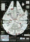
I believe the photo on the bottom is from Bandai 1/72 falcon's manual, if you're referring to that. I believe there was a link to that somewhere...Andre, is this a custom image you've created? It looks amazing.
I believe the photo on the bottom is from Bandai 1/72 falcon's manual, if you're referring to that. I believe there was a link to that somewhere...
Thanks David3. Cheersthis is the largest scan i have. found it online somewhere. probably from here or another thread at RPF. couldn't upload the full page pdf if anyone's looking for that so here's a link --millenniumfalcon_72_markinglocation.pdf
Welcome aboard Searun! As you saw, not many have tackled that ship...and at Studio Scale with accurate details. Seems like you're one of those person who will see it throughBrand new to this web. At 75, I have built many aircraft and ship models as a hobby. After reviewing this thread and other related information here, I have begun down the long road of attempting to build a Studio Scale Millennium Falcon. The design of this space ship is genius and is as creative and unique as the Disney Nautilus. Recently, I had an opportunity to discuss the incredible drawings developed and posted by a senior member of this forum and his team. As an x-aircraft mechanic that became an engineer, this work is first class. My goal is to build as accurate a model as possible. Using model wood working as a structure, brass plates will be uses as a skin. Some operating aircraft features are planed. Basic construction on the 4 ft. disc has started. I’ll post pictures as I proceed when I have something that is worthy.
One critical tolerance I need help on are some dimensions around the armor overlap edge, in case I am fortunate to kit-bash or obtain printed “greeblies” much later.
1. inside height dimension of the disc and mandible sides less armor skin thickness.
2. depth dimension of those two channels.
Saying this another way, in profile, the 2“ thick Mandibles slip into a 2.625” slot in the Disc. Both have detail that goes into side channels covered by overlap. Size of Geeble vary, but must be accommodated by a properly designed recess.
Thanks in advance, Searun
") Eager to see your next update
Eager to see your next update Thanks joberg.Welcome aboard Searun! As you saw, not many have tackled that ship...and at Studio Scale with accurate details. Seems like you're one of those person who will see it through
Well, since you gave your age, I believe you know "Old School Techniques" as well as "New School" ones. And it's great to straddle both worlds if I may say so myself (I'm 63, btw). So, yes...I'm sure your next update will show your skill level and your dedication to this crazy projectThanks joberg.
I have been retired for two years now, so dedicating time is possible. I am astounded at the skill you folks demonstrate with computer programs, use of plastic, molds, photography, and 3-D printing. While design drawings & construction have been my career, my hobby materials & model methods have not graduated much past aircraft fuselage & ship hulls using the old school kit methods.
That said, given excellent drawings, I can build. The bug has bitten me on this unique design. I will post pictures, but must have something that is worthy to show on a web forum that has such a high level of professional skill.
Thank you very much for the advice rbeach84. My build continues with tolerances that enable some adjustment were dimensions on some details remain questionable. The Andre Team overall drawings are my Bible. Can not have enough reference material when scaling up to a large model size. Minor measurement errors can “explode.” Working on a retractable landing gear system within the disc skeleton before starting basic skinning. Then will post some pictures. This thread sets a very high bar on craftsmanship.Sir, the Bandai Perfect Grade kit is indeed the perfect reference for the 5ft original miniature. Although expensive, the resale value would be solid if you decided not to build it too. Direct measurment.scaled up appropriately would give you what you need. The decal sheet is also spot on, the Bandai team really did the research. The 1/144 kit is not nearly as accurate... I got one just for this purpose though for my own 1/48 scale project. Best wishes doing fantastic work!
Regards, Robert
Thanks Studio Kitbash. Love your math.One approach is simply to take the Bandai Perfect Grade 1/72 Millennium Falcon, and multiply any measurement on it by 3.51152 to arrive at a perfectly scaled 1/20.5 ILM 1976 original.
Love the stories Searun! Keep us informed about those timesThanks Studio Kitbash. Love your math.
I went to school with a slide rule. Little known fact is that most nuclear power plant system mechanical & thermodynamic calculations were done using a slide rule to 3 figure accuracy until engineering companies started to buy a few hand held HP calculators that were then “share” with other departments. Obviously, not the reactor physics or pipe stress. God forbid however if you dropped your box of FORTRAN cards on the way to the computer room.
Wait until Quantum Computing makes its entrancewow, great photos.Sorry Andre, I should have shared these long ago but have only just finally got around to sharing.
Many pics are out of focus and dark but one or two may hopefully be useful.
Pics from Where Science Meets Imagination Sydney here.
Thank you Bjorn!Sorry Andre, I should have shared these long ago but have only just finally got around to sharing.
Many pics are out of focus and dark but one or two may hopefully be useful.
Pics from Where Science Meets Imagination Sydney here.