Studio scale Gold Leader Y-wing build info and questions for all you wise folk.

Flyscriber

Sr Member
RPF PREMIUM MEMBER
Hi Folks.
Heres another one for ya to follow if you fancy.
I'm am now a number of day's into the prep and armature design and build for another Y wing Salzo/Neisen kit.

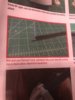
It comes with an ally flat plate 5mm thick and a rod with a machined flat in it to accommodate the plate. Both these parts were a bit below par for me to work with, so I have designed a laser cut metal internal armature to align the T struts as well as support the original Saturn V engine parts and the lighting/ battery pack.
I also had a spare full length rod from an earlier x wing project which I have shortened and ground out the flat plate support for the laser cut wing spar parts.
a1.jpg
a3.jpg
a7.jpg

These work really nicely and allow space for the engine wiring and battery insertion.
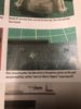
The holes are for threaded rods which align the T strips as well as the rear engine steering assemblies when I get to them.
b3.jpg
b5.jpg
b8.jpg
b13.jpg

These are all test fits to check clearance and the build methods for the assembly.
The nose cone is already partly assembled as are the engine cones made from original parts.
So heres my first couple of questions to the wise out in RPF land.
I would like to know the length of the T strips from the front to the front face of the rear steering vane assemblies ?

Also the orientation of the Heat sinks in the engine Nacelles (just so I get the small offset hole at the correct angles for Gold Leader, as we all know they varied a lot)

Gotta nip out now, I will post more later today.
Speak soon folks
 
I think the T strut is 13.25”. I’m traveling at the moment but off the top of my head, that’s right.
Will measure my Gold Leader when I get home later this week.
 
Wow - nice work, flyscriber! That's inspiring - my Gold Leader kit is still in it's box awaiting more of my time and attention. Like what you've done with the armature here, that's going to make me look at mine with similar thoughts...

Dan
 
Cheers Jkirkon, il look forward to checking the lengths out next to my thoughts from references.

The armature is looking good so far, the engine nacelles are sitting nicely on the armature stars with no deformation and the 4x 6mm rods allow for angle and droop adjustment etc.
The cages sit nice and flat across the tops so the T struts will be true and at 90 degrees to the horizontal. I'm looking forward to getting this thing clothed in plastic now.
f1.jpg
f6.jpg
f10.jpg
f12.jpg
f16.jpg
f19.jpg

A couple of spot welds later with the cages bolted up and carefully checked for square, the armature is test fitted with the parts and each part trimmed to fit. Once I was sure the parts were fitting ok I took everything off once more and spot welded the cages to the cross spar and checked alignment with callipers and 60cm lengths of 8mm threaded rod through the center holes.
So heres where I am now.
Engine cones from original parts
3 cone.jpg
half assembled with led lighting inside metal tube inserts.
1 cone.jpg

engine 2.jpg
turned inserts.jpg

More soon folks
 
That is some SERIOUS and HEAVY DUTY looking armature. The good news is you'll be able to play with your Y-Wing, drop it, throw it against the wall, and it still won't break! But that's ONLY if you can LIFT it in the first place, of course!

The official T-strut length is 346mm, and you want to use mm to get this exactly right. This is what Msr. Tox would say, Moff Eaton would say, Steven Neisen would say, and DaveG would say. If I'm wrong, they will correct me. If I am right, they will let this number stand without correction.

But if you're anxious that those look a little too 'stubby' (or 'a little short for a stormtrooper') in their overall eye-candy appeal, I think I can explain why.

I compare it to the elegance and artistry of the Fine Molds Y-Wing approach, versus the precise and exact replica Bandai model approach, in terms of design strategy. If you compare those two models, both accurate, and both at 1/72 scale, you'll notice they are different sizes and different lengths. The purists will say that Bandai had access to the originals and digitally scanned them and got an exact reproduction, and they are technically correct. But I think what Fine Molds did was to "interpret" the original and "idealize" it into not something different than the original, but into something that the original was in fact aiming for. If you look at them side by side, most people will tell you the Fine Molds version "looks better" because it just, well, looks better! (Ask young children which one looks more like a space ship they'd like to fly; that always produces very consistent results). But why, actually, does the Fine Molds version look better? It looks better, in my opinion, because they took photogrammetry of the reference pictures they had (perhaps of Gold Leader) and noticed there was a roughly 6% difference in the amount of T-strut that was "off the can" versus the amount that was "on the can" of the Saturn V can. In other words, the part that overhangs and extends beyond the Saturn V can is 6% longer than that which is on the can. This achieves several specific effects: 1.) It "just looks" better, as already mentioned, 2.) it makes the overall design more Fibonacci in the ratios of the parts to the whole, and 3.) it adds 6mm for a total T-strut length of 352mm which also has the surprising effect of making the overall model a lot closer to the Reference Books claim of 71cm for the total tip-to-tail length of the original.

By contrast, Galactic Resin models version builds out at 68.6cm in total length while the Neisen kit builds out to 69.85cm in total length when using the 346mm T-strut. When you ADD 6mms to the T-struts, you get a model that builds out to 70.45cm. Now of course the Reference books were just "rough averages" and good "quick measurements" by non-obsessed reference book writers. But which is more likely, that they rounded up to the nearest cm, or that they mismeasured the model by over 1cm? My money is on rounding up to the nearest cm.

In the end, it has to be a model you like, can live with, and "looks good" to your eye. My very strong advice is not to take my word for any of this, but simply to try both lengths, build one side with 346mm T-struts and the other side with 352mm T-struts and then do an eyeball comparison and decide which one looks better. Who knows, maybe along the way you'll find the actual exact length that none of us has found yet, because we still don't know exactly how long the 1.) fuselage should be, 2.)the neck should be, or 3.)the fuselage head should be, let alone 4.)the T-struts. So until these four factors come into a 10th of a millimeter accuracy, and do so in relation to each other, it really still is a bird open to interpretation. Keep in mind two that the original was able to come apart in sections, so with a removable head that was re-insertable, a certain amount of "play" in the overall length was most certainly a factor in why no two reference pictures of the Y-Wing seem to give an identical length. You are most likely building a "single piece" that does not have a detachable head, and so you'll have to make numerous minute numeric judgments along the way.

And also, for what it's worth: by the time you actually get to this stage of the build, you'll be very much nearing completion, and the thing will look so dang beautiful that you'll have stopped caring about how long it is and you'll just want to paint it and say it's done.

Also, I'm hoping my answer is satisfying enough that you'll let me purchase a set of your metal internal jigs for placing/spacing the T-struts inside the Sat cans. Those look absolutely genius, and bulletproof, and worth your asking price, whatever it is. I wants 'em!
 
Awesome stuff Studio Kitbash, I'm having a good chuckle to myself here. That's a great and overwhelming response to what I thought could be a slam dunk of a question. Nicely done. I must admit I have checked a few lengths using the assembled rear steering vane assemblies, and I must admit it looks better to my eye with the extra length on the rear. I'll see what other folks come up as we go along.
No worries on having a set of alignment stars made up for you. PM me if you want to know the OMG price !(its not that bad actually, just more than your average model bits).
Thanks again for a wicked and comprehensive reply :)
 
Over built and bullet proof, just the way I like it. I cant stand wibbly wobbly models you cant pick up for fear of distorting them. Sometimes its inevitable with thin structures, but these deserve an armature to last forever in my humble opinion.
Glad you like it folks.
 
FlyScriber,

I just noticed you are using the original Airfix Saturn V cans for the engine nacelles. If you would like to use the original Leggs pantyhose containers for the nacelle cones and tail shrouds, I have a few extra laying around. They will need to be cut to size.
I also plan on using original Airfix Saturn cans my my Gold 5 build. I’ll be using your armature ideas!!

Studio Kitbash’s superb answer jogged my memory....I used 346mm overall length for the T strut, but removed 6mm of the vertical portion of the rear of the T strut so that it fits into the tail shroud. I hope that makes sense, as I haven’t had coffee yet this morning!

PM me if you would like the Leggs containers and I’ll send them your way.
 
Now that I’m back home, I found the instructions I used, and measured the T-struts.
Mine are a total of 352mm.

The instructions tell the story, so here’s a couple of pics.....
 

Attachments

  • 610C7C7F-A44C-4FD4-A57E-17240096087C.jpeg
    610C7C7F-A44C-4FD4-A57E-17240096087C.jpeg
    1.2 MB · Views: 334
  • B8E36BA6-5108-4FA7-8907-B235CF2999DA.jpeg
    B8E36BA6-5108-4FA7-8907-B235CF2999DA.jpeg
    1.6 MB · Views: 335
Thanks jkirkon, PM sent.
That info is a great starting point for me to work with.
Does anyone know if there is a link out there in RPF land for the instructions?. I have found some fragmented details on some pdf's but nothing comprehensive enough to give a full overview.

Thanks once again to you all for your knowledge and time.
 
I have the original full PDF I saved down from the original release, if there is an Admin on here that can add it to the star wars media resources, as its too big to be uploaded and the wrong type to add to my media files.
 
That would be awesome Vacformedhero. Would it be possible to PM you as it may save some downloading issues etc.
 
I'll second that - if that full/complete version of the Gold Leader instructions could come to light again that'd be a huge service to the community. Thanks!

Dan
 
Here we are a few days later.
On Friday i did the boring but necessary engine nacelle final test assemblies for marking the positions of the T struts on the Sat can surfaces so i could position the greeblie sets and scale the small smooth panels on the Sat cans. Also to make sure I had enough surface left to open up the battery compartment on the Sat cans without leaving gaps around the cover plate later on.
s3.jpg
s7.jpg
s5.jpg


I sorted through the greebly packs, and dug out the best fitting versions of the precast greeblies for the cans so I can test place all greeblies before gluing them down. This will be right at the end of the build.
s4.jpg


I needed to check the Sat cans for removability whilst the greebs and pipes go on, as i will be drilling all the holes for the piping into the cans before the final fitting. This is to get the drill through the cans at the correct angle, as i know from previous experience that the body is just too fat to allow the drill the correct angle.
Then it was onto the final fitting and gluing of the wing panels incorporating the wiring. These were a royal pain, with the trailing edge tube half's not being very sympathetic to each other, they required some major sanding to make them fit nicely.
t5.jpg
t6.jpg
t7.jpg

Wiring was re-routed and zip tied into position as ell as being rewired to make battery insertion a breeze. Switch, used to isolate the battery from the remote receiver was positioned just rearwards of access hole and glued into place waiting for reinforcing before the cans are finally fitted.

So here's where I'm at now
t14.jpg
t15.jpg
t16.jpg
t17.jpg
 
This thread is more than 4 years old.

Your message may be considered spam for the following reasons:

  1. This thread hasn't been active in some time. A new post in this thread might not contribute constructively to this discussion after so long.
If you wish to reply despite these issues, check the box below before replying.
Be aware that malicious compliance may result in more severe penalties.
Back
Top