Star Trek TOS Dr M'Benga Medical or Daystrom Science Scanner Build

Corellianexports

Sr Member
RPF PREMIUM MEMBER
After purchasing one of the Diamond Select Tricorders with science scanner a few years back, I thought it would be fun to try and machine a full-scale scanner. It turns out the Diamond Select version is slightly smaller than the original and it uses a standard RGB (Red/Green/Blue) color changing LED. The original scanner used a small motor with a color wheel that provides six different colors, but I think it's a little overkill for this project, so I'm opting for a standard, color changing LED, instead.

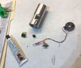
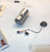
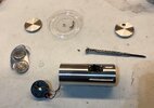
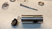
Here's all of the parts (sans the bolts) laid out. Most of the electronics can be found at any surplus store. The black tape is actually "floor" tape I found at a local hardware store:
Almost Complete Kit.JPG
 
Last edited:
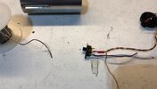
Before putting everything together, I start with the electronics. This is a very simple task because there's only one LED that needs to be wired to a switch and then to a battery holder. To help figure out just how much wire needs to be used, I'm going to start with the battery holder.

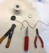
One trick to soldering anything is to use very thin solder wire. I special ordered this wire from All Electronics, but this can be found at any local surplus or electronics store:

IMG_3415.JPG

From left to right, I use a very small wire stripper, x-acto knife and wire cutters or "nippers". A small, 3v "button" battery is set aside for testing later.
Not seen in the photo is a soldering iron. I usually turn this on first thing and let it warm up while I'm gathering together all of the materials and tools.

I use the X-acto knife and wire cutters to split the wire and clean up the ends. The wire stripper is used to remove about 3/16" of casing from the ends of the wires.

Something I learned early on is to always add a small amount of solder to the ends of whatever I'm soldering together. In this case, it's the positive and negative terminals of the battery holder and the ends of the wires. Once that's done, I cut off a couple of small sections of wire wrap, placing them near the ends of the wires before soldering them to the battery holder.

IMG_3416.JPG
 
Last edited:
With the wires soldered in place, I use a heat gun to shrink the wrap, helping to solidify the connections to the battery holder.

I test fit the wires and the battery holder, taking some measurements. The battery holder is a little too wide to fit, so I use some 220 grit to remove some material on either side of the holder:


IMG_3422.JPG

After taking some measurements, the positive wire is cut for attaching the switch. This is standard procedure for any electrical project like this one. The negative terminal is always wired directly to the LED while the positive terminal is always wired to the switch:

IMG_3423.JPG

I use the wire strippers to remove the ends of the positive wires:
IMG_3424.JPG

Wires soldering the switch:
IMG_3425.JPG
 
As before, I use the heat gun to shrink the wrap around the terminals and wires attached to the switch.

Also, in this photo you'll notice that I've already attached the resistor to the positive end of the RGB LED. The positive end of any LED is the longer of the two terminals. We will want to note this before cutting down the LED terminals with the wire cutters. The resistor will also need to be cut down.
The idea behind using the resistor is to prevent the LED from using up the power in the battery too quickly. In some cases, it also prevents the LED from burning itself out, but this usually happens when the battery voltage is much more than 3 volts.:


IMG_3426.JPG

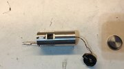
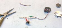
The LED is soldered to the ends of the wires with the shrink wrap already in place. Notice that I'm using the red wrap for the positive wires/terminals and the green for the negative wires/terminals. The small pliers come in handy for bending the wires and terminals so that they fit correctly inside the tube:


IMG_3427.JPG

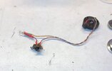
The button battery is installed temporarily so I can test the LED. If the LED isn't bright enough, it could be because the wires aren't soldered enough, or the resistor is preventing enough power from getting to the LED. The LED looks good, so the battery is removed before continuing.

It's easier to simply cover the entire LED terminal and the resistor with the shrink wrap:


IMG_3429.JPG

The heat gun gets used again. Remember to use it on all sides of the shrink wrap if possible.
It's done, so we can now prep for attaching the LED holder inside of the tube. Before gluing anything, I always use some low grit sandpaper on both surfaces. I'm going to use a small amount of contact cement to attach the plastic holder to the inside of the aluminum tube:

IMG_3430.JPG
 
Last edited:
I use the x-acto knife to trim the holder slightly so it fits flat, inside the tube. The holder is sanded slightly along with the rea inside of the tube where it will be glued. The LED is pushed into the holder:


IMG_3431.JPG

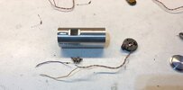
The switch has to be bent slightly to fit inside of the hole in the tube. It's a tight fit, but it will pop out eventually.
I use the top cap to align the hole with the placement of the LED. It's important to keep the tip of the LED aligned with the bottom of the cap and the hole, although the cap can be rotated slightly if needed.
Once I figure out exactly where the LED needs to be placed, the inside of the tube is sanded slightly.

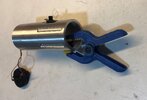
I apply a small amount of glue using a toothpick to the inside of the tube and then hold the assembly in place with a small clamp, making sure that the LED with holder is straight.
This type of clamp can be found at Harbor Freight Tools or the Dollar Store:

IMG_3432.JPG

The glue dries in about an hour, but I leave everything as is until the next day.
 
Last edited:
After letting the glue dry overnight, we're ready for final assembly. :)

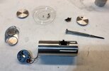
The screws used for this prop are basically the same size as the ones used on sunglasses and are so small that they had to be special ordered along with a special tap for threading the holes in the tube. I use a small, plastic lid to keep them in place. These are really easy to drop and lose so be sure to always keep them near the center of your work area so if they do fall, they fall onto the work area.

I carefully install two of the bolts into the switch that is already in place:


IMG_3435.JPG

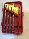
To tighten the screws, I use a 1/16", slotted screwdriver:

IMG_3437.JPG

With the screws tightened, I install the button battery and test the switch. The LED is still lighting correctly, so we're good.
I take the second switch and push it into the area next to the first switch:

IMG_3436.JPG

The two remaining bolts are installed:


IMG_3438.JPG

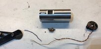
The battery holder with the battery gets pushed inside the other end of the tube.
Two, rubber, black "o" rings are wrapped around the ends of the end caps and lightly pushed into place. The rear cap is simply pushed into the end of the tube where the battery holder is housed. The front cap with the hole is aligned with the LED:

IMG_3440.JPG IMG_3444.JPG

I tried using a diffuser cap, light panel and a piece of clear plastic in front of the LED, but all of these simply reduce the amount of light emitted, so I found that just leaving it as is works best. It also helps to give the impression that something is being "scanned" which is what we want.

Movie:
 
Last edited:
The last part left is the black, floor tape.
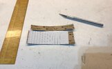
I use a template, ruler and an extremely sharp x-acto knife to cut out the right size material:


IMG_3448.JPG

I remove the backing on the tape and slowly wrap the tape around the bottom of the tube, keeping it as straight and lined up with the bottom of the tube as possible. It's not clear where the seam line is in the reference photos, but it doesn't appear to be anywhere near the switches or the right side of the tube.

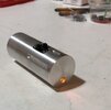
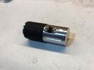
And it's done:


TOS Scanner Prototype 1.JPG TOS Scanner Prototype 2.JPG

Movie:

 
Looks great and thanx for the step-by-step which might come in handy just in case I get the kit instead of the requested assembled unit. (I'm still on your "Build" list, yes?) Best. Mike.
 
Last edited:
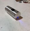
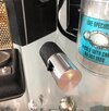
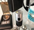
After re-watching "The Ultimate Computer" and "A Private Little War" on blu-ray, I realized that the light is actually located closer to the switches, so I moved it to what looks like the correct position. It does look like the light may be placed slightly differently in each episode, but here's what I came up with:

IMG_3525.JPG IMG_3524.JPG
 
After re-watching "The Ultimate Computer" and "A Private Little War" on blu-ray, I realized that the light is actually located closer to the switches, so I moved it to what looks like the correct position. It does look like the light may be placed slightly differently in each episode, but here's what I came up with:

View attachment 1584461 View attachment 1584462
Cthulu is in the details—I'm sure that it'll be wunderbarful. Best. Mike.
 

Your message may be considered spam for the following reasons:

If you wish to reply despite these issues, check the box below before replying.
Be aware that malicious compliance may result in more severe penalties.
Back
Top