Star Trek III through VI Tricorder

BajaTym

Well-Known Member
RPF PREMIUM MEMBER
Greetings RPF folks, I’m a longtime lurker that recently picked up a 3D printer. I’ve been playing with it for about a week and have decided to dip my toes back into replica crafting (I’ve been on a 15+ year hiatus do to work and family).

To set myself off in the right direction I’ve decided to build something that I’ve not seen in a long time, a Star Trek III-VI recorder. I’ve been digging around and have found only a small amount of reference material online so I’ve had to rely on a 20+ year old copy of Mr. Scott’s Guide to the Enterprise and Felgacarb’s 2012 “Star Trek III Tricorder - 3D Print Version - Complete!” post.

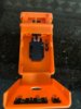
Using 123d I established the basic frame work:

tricorder-1_zpsvwu1ovmj.png

Getting closer…

tricorder-2_zpski5wgoqn.png

More closer…
tricorder-5_zpsvkgxjsxy.png

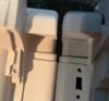
I can’t seem to wrap my mind around the back…

tricorder-6_zpsliarqmyc.png

tricorder-8_zps5ha93yy2.png

If anyone has some good resources such as true dimensions, photos and anything else I would be grateful.More to come… (and thinks for the medium!!)

Cheers -- James
 
Edit: I’ve decided to mirror my TFW tricorder build here. It’s somewhat different than my original intent, but still focuses on the TOS movie-era tricorder. The posts start just below the TFW comments.

Enjoy.


Sorry that I abandoned this project a long time ago, but this is the first time I've been back to this link in years... I actually forgot about it. Anyway, those who care may be interested in my TOS Movie-era Tricorder build over on the TFW.

-- James
 
Last edited:
I believe it's The Fleet Workshop, which is a Star Trek specific prop forum. Unfortunately, I don't have an account, and it looks like they're not accepting new ones. I shouldn't have just lurked there for so long :(
 
I used to lurk there too but about 2 months ago they locked it down so that only people with an account can even see it and I don't see anyway of even applying for an account.
 
Same. I check back there every once in a while to see if it's opened back up, but so far no luck. I also had trouble signing up for Trek Prop Zone, the only other semi popular Trek prop forum I've found. Basically, the RPF is all I can get to.
 
I get the impression that the lockdown is intentional, but it's hard to tell since I can't read any threads hah. Maybe you could see if there's a thread explaining it?
 
I won’t bore you with the details of why I shelved my previous build, just know that my original goal was to make a screen accurate replica of the unit in the SFS unit.

Now it’s 2019 and I’m more interested in making something a little more interesting. So after a lot of brainstorming I’ve decided to build a hybrid of sorts that will combine selective elements from each of the respective TSFS/TFF/TUC designs. To do this I’ll be keeping only the elements of each movie era device that I like best, along with adding my own pop-up mechanism, electronics, and a few other tweaks.

As promised above, the next several posts are copies of my thread on the TFW. I recommend that you read through them before answering any questions posted as some answers have already been found.

Thanks for the interest and hope you enjoy the build. -- James

Part 1: Study and design
Even though this isn’t going to be a screen accurate build, I’m still going to remain faithful to the overall design. With this in mind the first thing I did was study the images I have in hopes of identifying any parts that may have been kitbashings or found objects. Unfortunately the only parts I was able to identify were the LEDs, buttons and strap mounting points; though I’m fairly certain the center disk is a wheel taken from a model kit, specifically the Tamiya RENAULT RE-20 kit used for for the Klingon tricorder, but I can’t be sure until I acquire one.

renault.jpg


Also, I’m almost positive the section highlighted here was cannibalized from an existing item, it just looks like something real-word… any ideas?

screen.jpg


Off the shelf, and from my knowledge screen accurate items:

5 ea - Grayhill buttons, manufacture PN: 87CC3-201, ~$5.50 ea

IMG_6819.jpg


3 ea - 10 Segment LED array, no specific PN, ~$3 to 5.00 ea (depending on the color used)

IMG_6816.jpg


4 ea - Square (8.89 x 8.89mm) LED Light Bar, Kingbright, manufacture PN: KB2755YW, ~$1.80 ea (I’m using yellow)

IMG_6815.jpg


2 ea - Generic Camera Strap Lug, ~$2.00 ea
UPDATE: Current price as of 22 Mar is $3 ea. Can be purchased at DAG Camera Parts

IMG_6817.jpg


2 ea - Triangled rings, ~2.00 ea
UPDATE: Can be purchased from B&H Photo and Video (or do a search for Camera Strap Split Rings)

IMG_6818.jpg


1 ea - Wheel/hub, 1/12 Scale Tamiya RENAULT RE-20 TURBO F-1 Kit, ~$50-$500

Wheels.jpg


My first modification was to rearrange the LEDs on the face of the scanner head. In my interpretation of the device, lets just call it a Type B Tricorder, the front facing LEDs are there to perform the various sensors and atmospheric measuring functions and nothing more. After playing with different layouts my feeling is that this arrangement gives the face a more balanced appearance and helps to support the idea that each LED is indeed performing a specific function that requires the head unit to raise out of the body to perform their tasks.

front.jpg


The second modification I’ve made was to replace the rear viewer area/box with a 1.5” color OLED screen. Unfortunately I had to enlarge the screen housing to accommodate the display. Initially I was just going to hold off until I found the proper sized screen, but in the end I couldn’t find anything more suitable so it’ll have to do for now.

screen.jpg

lineart2.jpg
 
Last edited:
Part 2: Making sense of functions

Since I’m installing an actual screen I need to figure out what it’s going to display, how the user is going to interact with it, and the functions of the 5 physical buttons on the face.

While examining the interface and button layout it occurred to me that the original designer couldn’t of had much time to focus on functionality; it seems so unintuitive and impractical. I know it was just intended for a few scenes in TSFS, but it’s a little baffling to me. Regardless, I love the esthetic and design… back to the front facing/unlabeled buttons, I suppose a properly trained crew member would be familiar enough with their equipment to know what each button does without having to look at them. Being that there’s 5 tactile buttons I’ve decided that 1 would be a dedicated power button and the other 4 will be figured during the programing phase.

buttons.jpg


  1. Power
  2. (Placeholder) Biological
  3. (Placeholder) Geological
  4. (Placeholder) Meteorological
  5. (Placeholder) Library
menu.jpg


Screen/Interface designs
This has proven to be more difficult than I originally thought. Not much exists graphically in the trilogy movies and I’m not a fan of the disc shaped info displays Mr Okuda designed for TVH onward. I’m thinking it needs to be simple with some selectable options.

So I’m thinking…

a9bfdca1c0aeb71bb5afe6276c612f92e01cb6a4.jpg
b7b0ff9258eddc806d2be490594781b26debb2a9.jpg


Here’re 3 examples of how the screens MAY look, these were thrown together very quickly…

23a2f080a3384cde26f8222e8559fa07c2c916ea.jpg


e7567fe46c4a760a7e7d1c8ebc521e987610b226.jpg


a6274dd78d2d8f8b842242637531cd44406d5552.jpg


More to come...
 
Part 3: CAD Files and Design

Using Illustrator, 123D, and my archive of screen used tricorder photos, I created a reasonably accurate model.

Taking shape…

back-side.jpg
front-side.jpg


I’ve increased the back screen/viewer area slightly to accommodate the 1.5” OLED screen I’m using.

screen.png


I was debating whether to use a Raspberry Pi or an Arduino to drive everything, but since this will be my first build I’ll stick with what I’m most familiar with, the Arduino Mini Pro. I have several just sitting around and they’re very inexpensive

So when designing the internals I needed to account for mounting the Arduino, a sound FX board, amp and speaker for the audio, an SD card reader to hold all the data, a stepper motor to raise and lower the sanner head (I may use a servo, I’ve not decided yet), and a few 4017 ICs to animate the LEDs. At the moment I’m planning on brewing a few custom PCBs to hold and connect all of the components in place.

Also, since the Arduino doesn’t actually have a physical off switch, I’ve added a slider switch to the back in order to kill the power when the MC isn’t in use. I’m also wanting the front face to hinge open for easy battery changing. Lastly I might also try and outfit the interior with a futuristic skin to cover the contemporary electronics… but we’ll have to see how it goes.

open.jpg


More to come...
 
Okay, my kit arrived today, I can 100% confirm that these 2 parts were indeed used to make the center disk (not sure if it’s supposed to be a tuning knob, speaker, or some other sensor).

renault-jpg.jpg


[Close up of TSFS screen used tricorder]

image019.jpg


[Kit parts number D1 (front wheel) and D9 (can assembly)]

fa7ac3e1bec7bf8245ffd5d54e251623767e8e91_1_690x454.jpg


I simply love all of the SFS props and all the little race car parts they used to build them. Now that I have the Renault kit I’ve added the large Klingon tricorder to my build [bucket] list.

Cheers – James
 
Part 3: CAD Files and Design, continued…

So far I’ve printed and assembled 2 proofs of concept for study purposes.

After reviewing the first print, I decided to make several mods; basic tolerance adjustments, a couple of scaling tweeks, and most importantly I decided to scrap the stepper motor idea and go with a physical spring mechanism. The stepper setup I designed made it impossible to remove the scanner head once it’d been installed. So being that I’m no engineer it just makes sense to me to keep things as simple as possible.

So with the stepper gone I played around with several spring concepts and for a brief time, I considered various methods, to include what I’ve seen others use (such as Rich and Scott). But in the end I concluded that those particular designs would be best for a screen accurate build and would take up too much internal real estate. After rummaging around “Ye Ol Scrounge Tub” in the garage I decided to use a trimmed down toilet paper roll holder/spring and a cabinet spring latch.

So to open it, you push down and the scanner head smoothly pops up. Then to close it, just push down and it latches closed. Of course this is not what I’d use on a screen accurate build, but it should work here.

cef1b1d787ba79dfd2d2b4363acc976fe438edf3_1_666x500.jpg


9fd6cf6f20d4f32e67df59cc1e7a7e2ec1f99fa6_1_375x500.jpg


e5fa93b5ae45e564e19a3828b78a7f4ddf59c783_1_375x500.jpg


4daf7c012d23ed8988d1d3eb8a7b1f9faf016b96_1_375x500.jpg


bb477bef67ed633620bbdb65c7ed25586935f14d_1_375x500.jpg


I’m currently working on removing the print lines from the second print, then I’ll be moving onto the electronics.

Cheers – James
 

Attachments

  • bb477bef67ed633620bbdb65c7ed25586935f14d_1_375x500.jpg
    bb477bef67ed633620bbdb65c7ed25586935f14d_1_375x500.jpg
    126 KB · Views: 101
Part 3: CAD Files and Design… continued

Okay, last week I was able to check my design measurements against an actual casting; while my build is remarkably accurate, it’s approx. 6 mm wider & taller.

In addition there are several noticeable dimensional differences; louver/grill height and corner-curvature, the overall dimension/shape (even with my over-scaling accounted for) of the viewing scope, and thickness of the main body/housing. But considering all that I had was photos, I think it turned out pretty good.

Mine is on the right (dark grey):

8536a2140f99cb5d01dc3f6ae24519226984727b_1_496x500.jpg


147e09418969f436f0af7cd8ebab281c2c95d2f0_1_552x500.jpg


f06ef7f0b2429695da4f64dcd15d350e2da408b1_1_503x500.jpg


Now normally my response to this type of comparison would be to stop, make note of every difference, go back and mod the CAD files/correct every error, then reprint everything as needed. But I’ve reconsidered since this was never intended to be screen accurate anyway. Instead I’ve decided to just make note of the needed adjustments and press forward with this print and incorporate the changes into a future screen-accurate build.

Anyway, as it stands now, everything’s been cleaned and prepped, the ribbon cable has been glued on, and the body primed. So I have a little body work to take care of and if all goes well I’ll be laying down my first coat of color tomorrow.

a1adcec1cf7ff389524d2e30873923a6a1b68e3c_1_619x500.jpg


f76e201e770d0263efe912657e53d893670bfb4d_1_545x500.jpg


Thanks for looking… and loud shoutout and thanks to Scott! – James
 

Attachments

  • bfefa0d31523f9d76860fe3280e53a801871ce8f_1_536x500.jpg
    bfefa0d31523f9d76860fe3280e53a801871ce8f_1_536x500.jpg
    126.2 KB · Views: 141
Last edited:
With all the body work is done, sorry no pictures, I need to pick the colors. From what I can make out the movie-era equipment seems to range in colors from:

SFS: Gunmetal shell; black scanner head and louvers
TFF: Dark metallic grey shell; black scanner head and louvers
TUC: Gloss black shell; flat black scanner head and louvers

Anyway that’s what they look like to me, but I’m not sure. If anyone knows the colors I’d love the help. Well until I know for sure I’ll be pressing forward with the colors I have on hand:

Tamiya Light Gun Metal for the shell
1e85a107ef9e6784aa806dd9d30df863ffa4b911.jpg

Either Tamiya black or Gun Metal for the scanner head and louvers.
6c2936c57074d5314731cca44711683956006d77.jpg


I’m hoping to get to the electronics tomorrow or this weekend.

Cheers – James
 
This thread is more than 3 years old.

Your message may be considered spam for the following reasons:

  1. This thread hasn't been active in some time. A new post in this thread might not contribute constructively to this discussion after so long.
If you wish to reply despite these issues, check the box below before replying.
Be aware that malicious compliance may result in more severe penalties.
Back
Top