ST: Discovery Communicator build

Kokanee

Sr Member
RPF PREMIUM MEMBER
I have a spare adafruit sound board kicking around, and this (https://www.thingiverse.com/thing:3655482) set of files for a STD Communicator caught my eye. I wanted more of a "kit" experience, so I ordered all the parts from shapeways in various materials; with some chosen for dimensional accuracy but others chosen for aesthetics. I'm working from reference photos of the real prop, as well as the blueprints put out by CBS:

61d-oOwhPaL._SL1024_.jpg


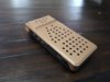
Had a few moments today so I kicked things off by doing some paint on the antenna and back cover/delta assembly:

IMG_20191005_174236.jpg


IMG_20191005_174214.jpg


I also have the wiring harness all done up except for the lights. I'll post up pics once I have that done. In the meantime I think the back cover looks quite nice!
 

Attachments

  • IMG_20191005_174236.jpg
    IMG_20191005_174236.jpg
    6.1 MB · Views: 145
Very nice. I can't wait to see the finished piece. The props are about the only thing I like about STD and unless you make them yourself or get a 3D finished one there is nothing out there.
 
Image2.jpg


Designed some buttons for the sides, hoping to get these printed in a rubber-esque compound.

IMG_20191006_115743.jpg


Quick rough assembly of the internal components, minus lights. I HAD ordered a metal internal chassis (for the weight), but unfortunately it was out of spec when it arrived so reordered in resin and awaiting it's arrival.
 
Like many have said here looks great coming along nicely. Wish they come out with a blue tooth version or just electronic one hint, hint Wand Company or another solid manufacturer out there. Look forward to seeing your next posting.
 
A lunchtime of fine tining the fitment of the buttons and accessories yielded this:

20191017_125745.jpg


The aluminium looking buttons etc are in fact actually sintered aluminum, they have a nice feel to them. It's starting to look more and more like a communicator each day. Have to give the main body another coat of paint as it turned out too light for some reason.
 
20191023_122652.jpg


Made some more progress over lunch, with the subassembly of the chassis complete, it was time to start wiring the lights for the screens. At bottom left is the adafruit soundboard with a microUSB to USB-C adapter attached, so I can recharge the prop without opening it up with a common USB-C cable. Due to space constraints, the 2W round speaker was removed and 2x1W oval speakers were soldered in.

20191023_130418.jpg


20191023_133345.jpg


I used six microLEDs which are actually designed for model trains+scenery etc for illumination, and attached them to a scrap piece of lexan which was scuffed up with sandpaper. Both to provide some standoff distance and disperse the light from the LEDs as they are pretty intense!
 
This is looking really good! Excited to see someone build one :)

Good choice on the spot you cut open for the charge port. That slot on the communicator body roughly lines up with where the iPod nano's lightning port is, and I initially assumed that was how the originals were charged, but after closer examination of the prop that went on convention tour it ended up being not open to the interior. But it functionally makes a lot of sense to use it.

When I eventually build mine I may end up using one of these edge-lit backlight modules:

It's around the right size, and can be trimmed. Plus no "hot spots" in the illumination.


Just ordered one I'll have it in a day, hot damn that's a way better solution. Thx.
 
Awesome! The only part that can't be cut is the LED on one end - the rest is a plastic (acrylic?) light diffusing panel. So you can trim it with a dremel or saw or whatever and paint the cut edges white (or tape over with white vinyl). I'll check later - it might not even need to be trimmed.
 
yeah it will be, the dimensions for the communicator that are available for "guts" is 44mm wide x 85mm long x 12mm depth. It will just fit width wise, but the long end will need to be trimmed.

Thanks for the deets!
 
So my light panel arrived, sadly it's not going to work for this project. Being almost 4mm tall, it takes up too much space in the chassis when you mount the adafruit soundboard and battery on top of it.

Going to wire the existing light in over lunch, and glue down all the components. Next week, getting the antenna hinge system working and the momentary switch to get everything to light up + sound when you open it up.
 
Untitled.png


So here's the guts so far. At the bottom, unseen are the lights. On top of that is a adafruit audio fx board (16mb w/ 2x2w amp). Sitting to the south of that is a lipo "backpack" board that allows for recharging via the audio board's microUSB port (i've attached a USB-C adapter to that to be future proof). Left of that are the two 1w speakers, and sitting on top dead centre is a 500mah 3.3v battery. It all JUST fits in quite nicely while leaving some room for the hinge and switch assemblies to come.
 
Back
Top