Been wanting to make one of these for some time now and with con season looking likely to open up towards the end of the year I figured this would be a good time work on this build.
The plan for version 1 is to have the following:
- Working screen that will show random still images
- Two buttons - (1) on/off (2) screen sleep/on and next image
- Rechargeable battery (Lipo)
- Real time clock
- mini speaker to do simple beeps when buttons are pressed
The plan for version 2 is to upgrade:
- Replace images for video
- replace buzzer for speaker
- Replace beeps for audio clips
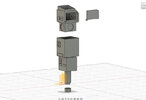
I've completed the modeling in Fusion 360. My intention is to have the upper and lower sections secure with magnets for ease when I need to take take things apart for upgrades/maintenance. The access panel in the top/back is to gain quick access to the battery for recharging.
Here some pics showing the comlock in 360 -


Here some prints I just completed to test out fitment and spacing.

I'm also starting to work on the adruino code on my breadboard. I'm using a standard sized uno but the final version that will be installed will be a mini microcontroller. Already have the images and the functionality of one of the buttons in. I'm using a 1.3" 240x240 TFT.

Lastly - I dont recall where I found the drawing for the comlock, but I suspect it may have been here on RPF. In any case a shout out to Rob Antonishen whom I believe authored the diagram I used when made the model.
More to come.")
The plan for version 1 is to have the following:
- Working screen that will show random still images
- Two buttons - (1) on/off (2) screen sleep/on and next image
- Rechargeable battery (Lipo)
- Real time clock
- mini speaker to do simple beeps when buttons are pressed
The plan for version 2 is to upgrade:
- Replace images for video
- replace buzzer for speaker
- Replace beeps for audio clips
I've completed the modeling in Fusion 360. My intention is to have the upper and lower sections secure with magnets for ease when I need to take take things apart for upgrades/maintenance. The access panel in the top/back is to gain quick access to the battery for recharging.
Here some pics showing the comlock in 360 -
Here some prints I just completed to test out fitment and spacing.
I'm also starting to work on the adruino code on my breadboard. I'm using a standard sized uno but the final version that will be installed will be a mini microcontroller. Already have the images and the functionality of one of the buttons in. I'm using a 1.3" 240x240 TFT.
Lastly - I dont recall where I found the drawing for the comlock, but I suspect it may have been here on RPF. In any case a shout out to Rob Antonishen whom I believe authored the diagram I used when made the model.
More to come.