Slothfurnace's ROTJ Luke saber - Crystal chamber, detachable blade

slothfurnace

Sr Member
RPF PREMIUM MEMBER
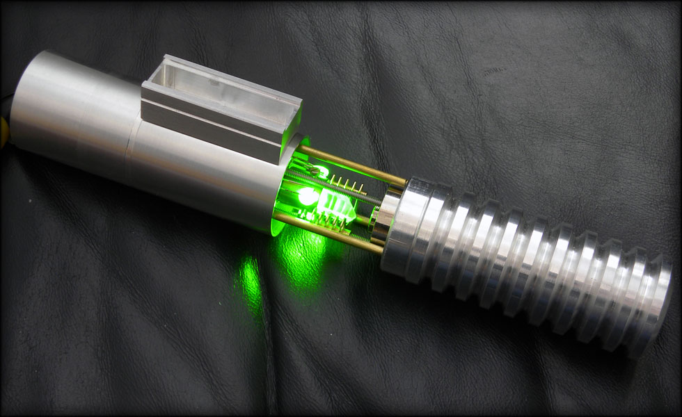
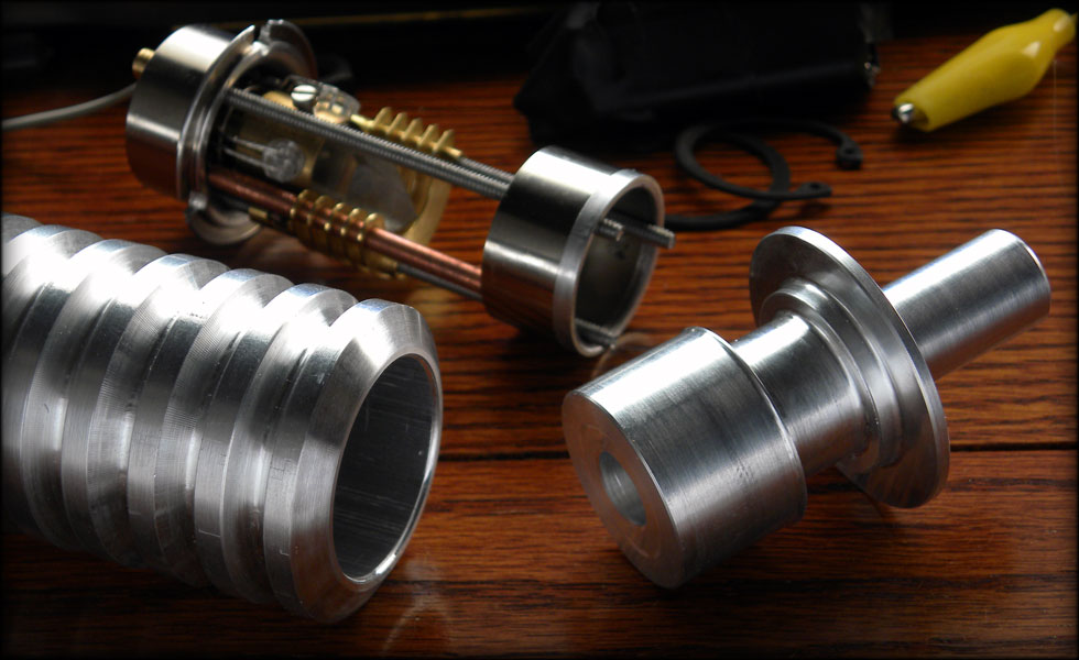
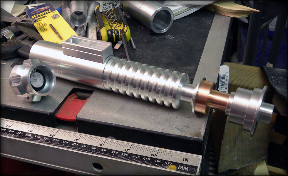
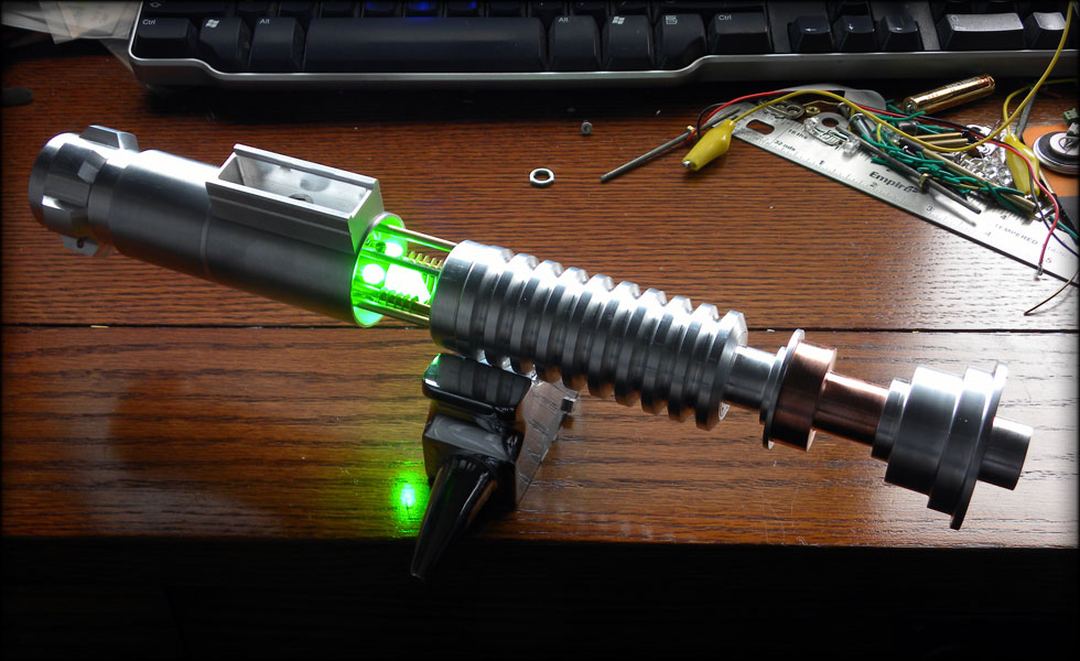
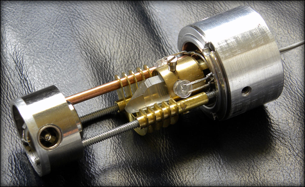
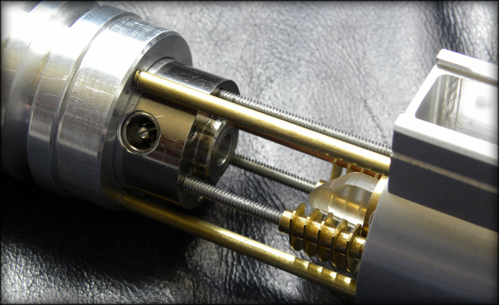
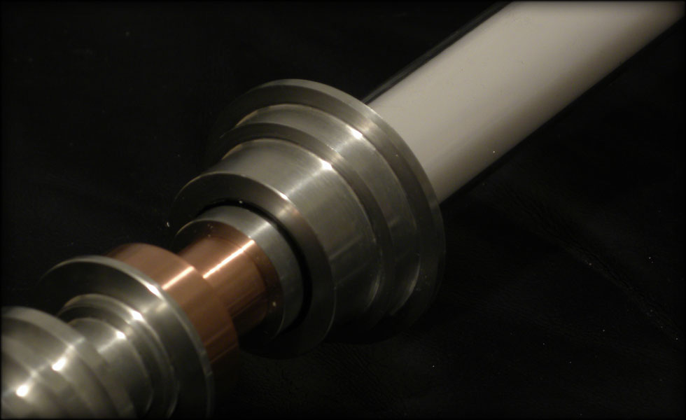
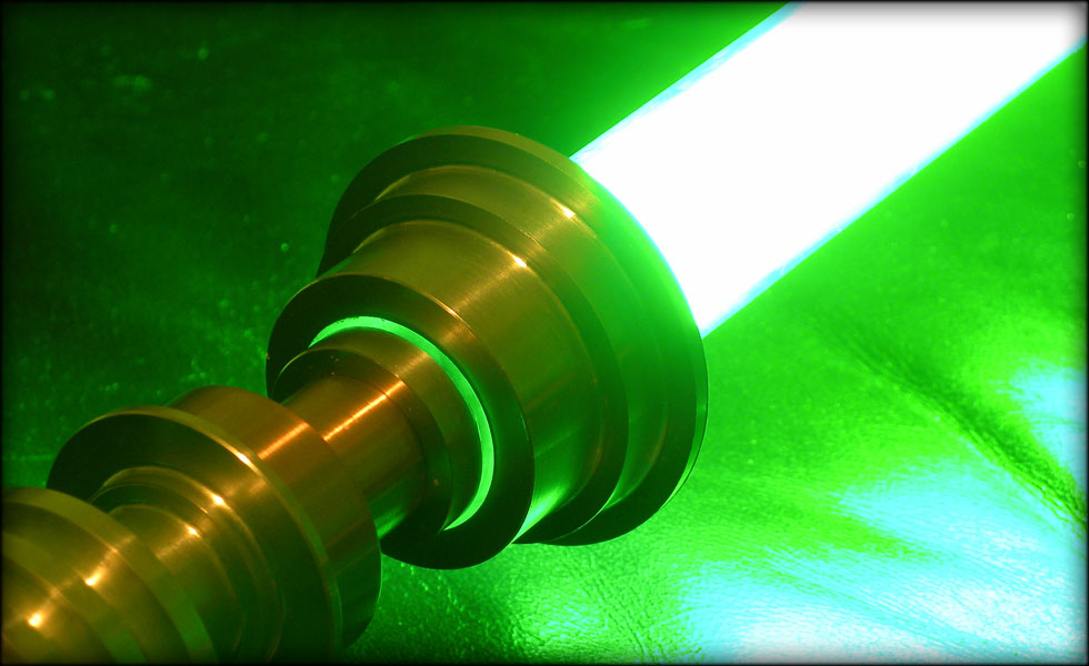
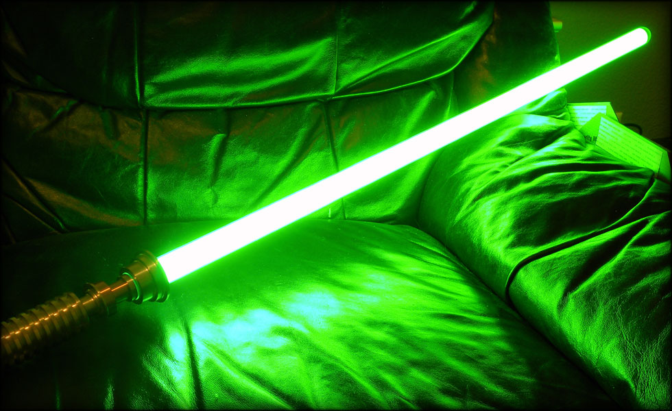
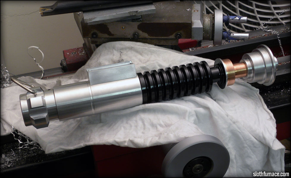
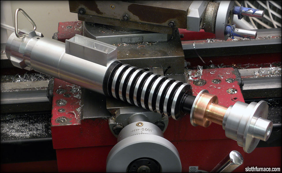
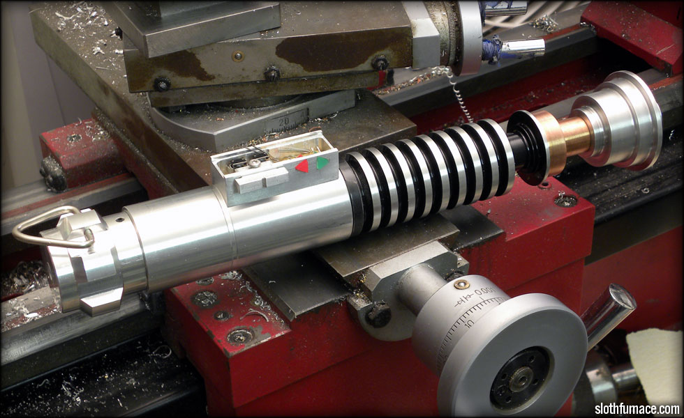
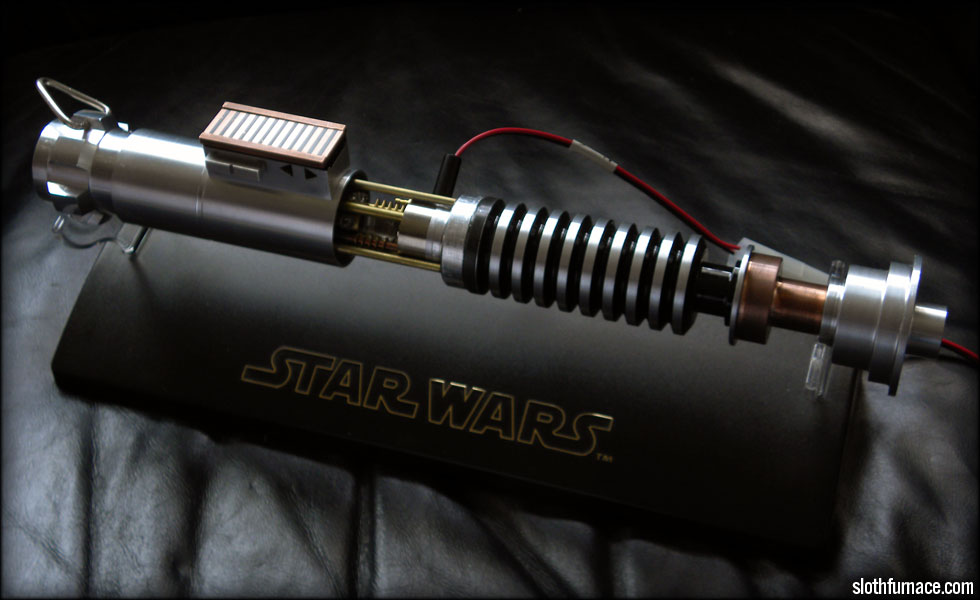
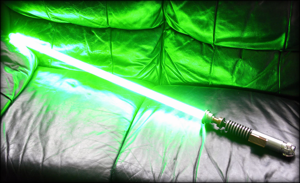
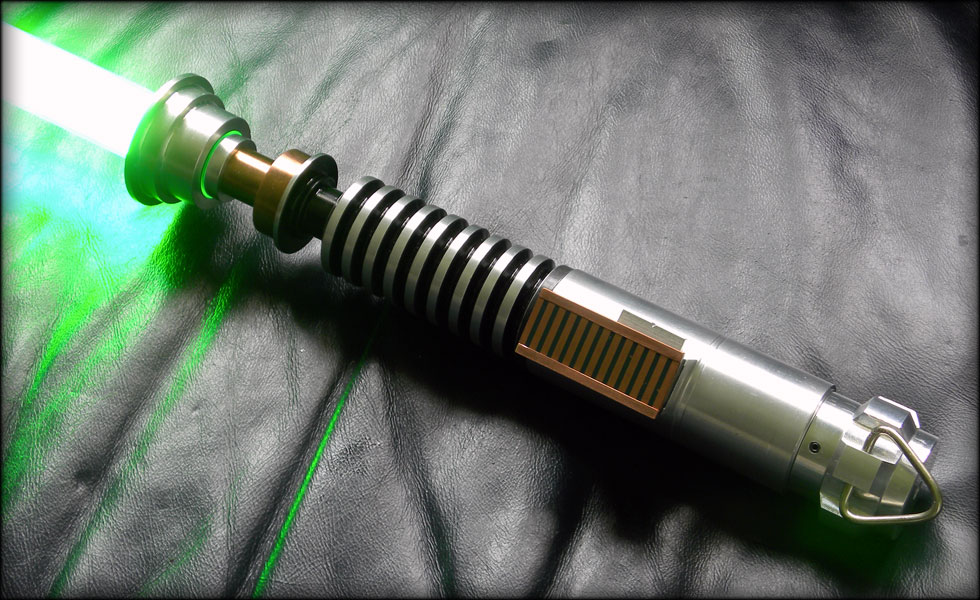
It is time now to post this saber, I'll be bombing this thread with posts till I get the bulk of the build log in here, but this is a Return Of The Jedi Luke Saber, with crystal chamber, thin neck, and detachable blade.
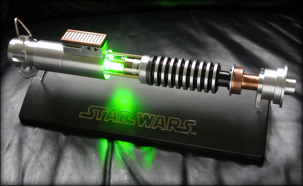
086.jpg


The build log as follows was between November 1, 2010 and December 24, 2010. More can be seen at www.slothfurnace.com

000.jpg


My initial sketch of the project, I *think* I can get it all in there.

001.jpg


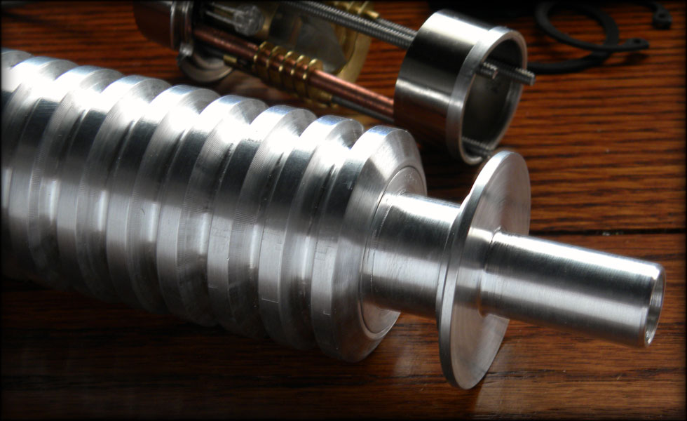
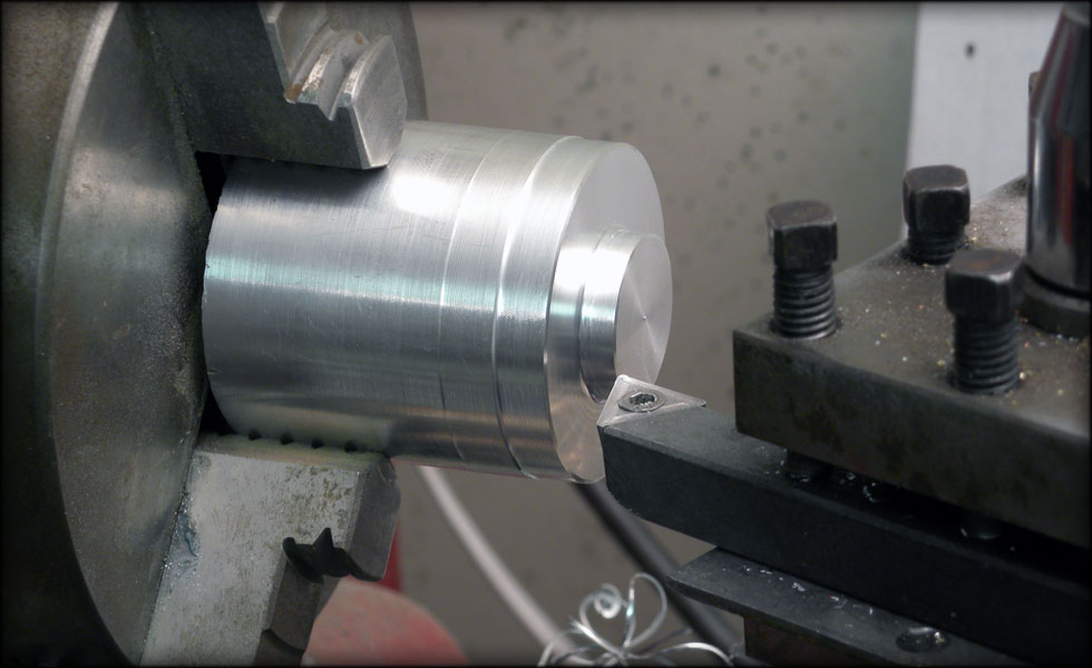
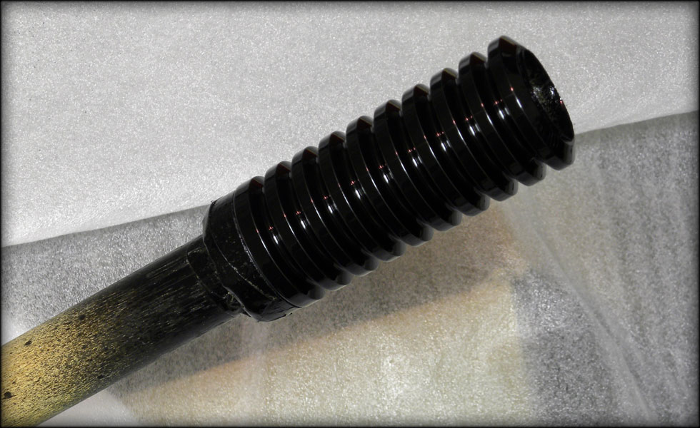
I begin with the key to the project, the collapsable grip section, first I must replicate this part, in hollow 1.5 inch diameter aluminum.

002.jpg


After I got my first groove cut, I measured out 0.32 inches for each successive groove, marked it lightly with my lathe, on each side of the groove, thereby giving me a place to "color in the lines" so to speak, and to take the groove down to a set depth on each ring.

003.jpg


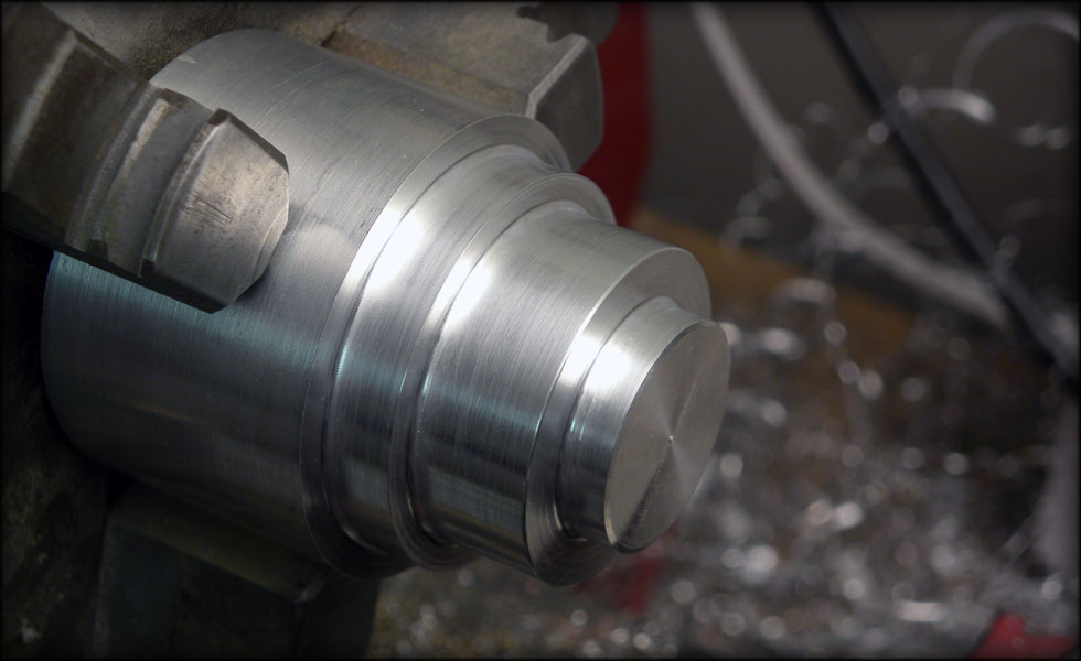
Here are the grooves cut, I have a bit of chatter in one or two, but that's easily solved with some sandpaper. The grooves will be painted in the end, so it won't matter too much. I also made sure to use a slightly more rounded tip on my cutting bit so as to let the inner diameter inside the grooves leave enough material to be strong, with the grip section being hollowed out to one inch.

004.jpg


Here I turned the grip section backwards to cut the smaller diameter behind the grooves. This will fit inside the main rear grip section underneath the control box, and be cut so that I have a retaining ring to let my rods go through for the collapsing bit.
 
Last edited:
005.jpg


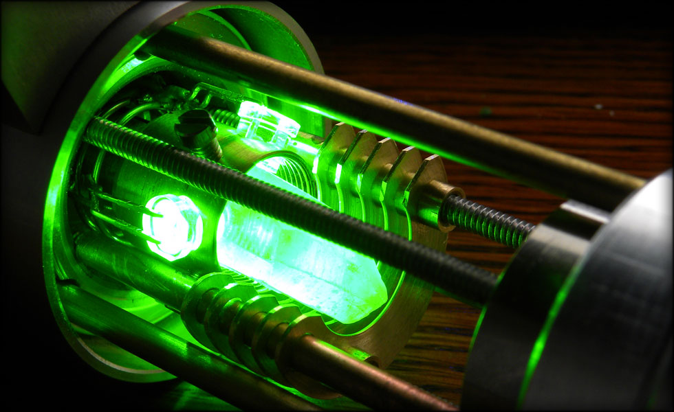
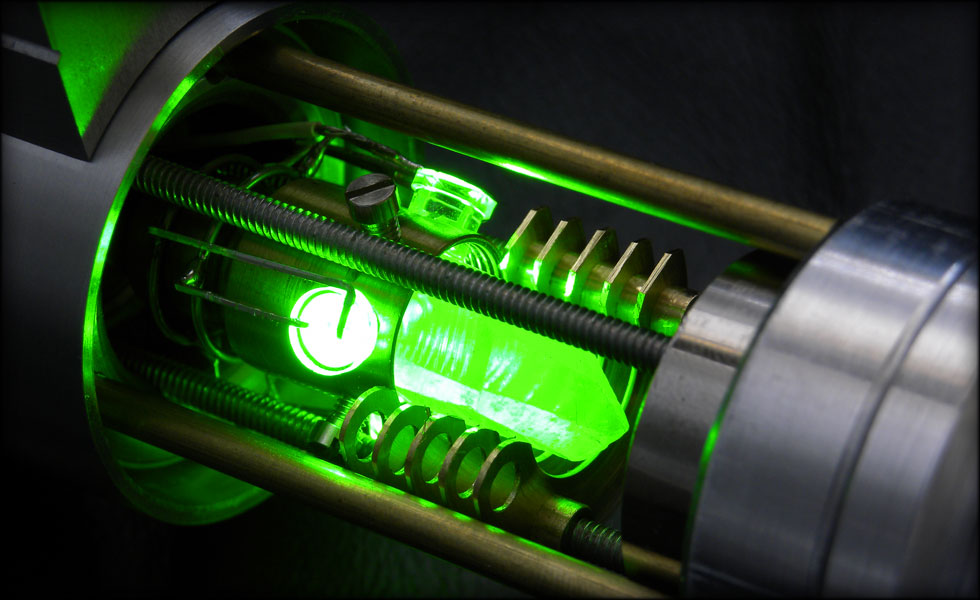
I got one of my first crystal candidates in, and test lit it with the green high power LED. It transmits light very well, much better than the tourmaline I had tried earlier. This is a double terminated clear quartz.

006.jpg


Playing around with greebles for the crystal chamber. I love this brass air brake ferrule.

007.jpg


At this point, I begin the LED string. The LEDs I am using are extremely bright, can put out from 7200 mcd to 21000 mcd at 525 nm. That's MUCH brighter than anything I have used to date. To begin the process, I use my flat needlenose pliers to fold out the leads so that they are straight out, and as flat to the bottom of the LED case as I can get them.

008.jpg


Now, I use my regular needlenose pliers as both a spacer, and to hold it while I bend each lead back down. I try to make as close to a 90 degree sharp angle as I can, while holding the lead in the same spot each time, as the pliers are tapered.

009.jpg


Here, I have my LEDs bent and prepped for the next step. Consistency here is key, as it will make a big difference in the straightness of the LED string.

010.jpg


Next step, folding over. I use a scrap piece of shelving track for this, so my bends are the right angle and length every time. Again, consistency is key here. It won't be perfect, but the closer to uniform you get, the better.

011.jpg


Always make doubly sure that the bends here go the right way. I always point the "arrow" part of the LED up when I bend, so that the positive and negative leads always go the right direction. Saves me from having one reversed.

012.jpg


Now that they all are bent, it is time to assemble them together. This is one of the more tedious steps, but it will be worth it when they come on for the first time.

013.jpg


Assembly, here I make sure my leads are all correct, positive down one side, and negatives down the other. I will assemble six sets of 12 to 14 LEDs like this, depending on length of blade. Pass one LED's leads through the shoulders, and bend up and crimp with needlenose pliers.

014.jpg


This is a section of 12 LEDs. This will go on the rest of the strip I already have made after soldering and trimming.

015.jpg


To solder, I have a little anvil with a magnet on top, this keeps my LED string section in place while I solder, and the magnet is also handy for when I trim the extra leads off the sides. The magnet collects the leads, instead of them getting in my carpet, and in my foot.

016.jpg


A completed section, soldered, trimmed, ready to join the others.

017.jpg


Here I have several sections placed into the diffuser foam tube, and test lit. It is unbelievably bright, pictures don't do it justice. It hurts to look at it without the diffuser foam.
 
018.jpg


So now it's come time to put one of my theories to the test. I think that if I cut the long end of the drilled portion of the grip off, and use that as a template to transfer my hole pattern to the other pieces, I will be able to line up my holes straight enough so that the rods do not bind up when collapsing the chamber. In the pic above, you can see the indentations of the drill on the main body where I passed the drill bit through the template.

023.jpg


Here is the template cut off the other grip section, flattened and set on top of my main handle. I cut an interior step to let this template fit snug into it, and took it to the drill press to transfer my holes.

019.jpg


I'd say it worked! The rods only fit one way, because the holes are *slightly* imperfectly spaced, but they are STRAIGHT. Which is what I need for me to be able to open the crystal chamber.

020.jpg


Like so. I will have about this much room to open the chamber, and the pommel/battery pack section will go behind this main body section to finish out the length of the handle.

021.jpg


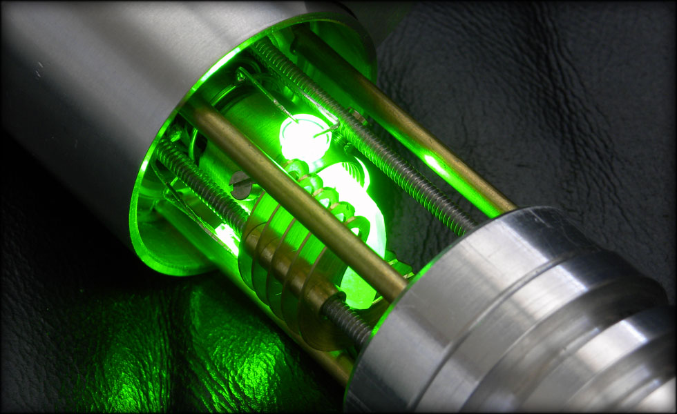
I have about a one inch diameter by 3 inch long section to fill up with crystal chambery goodness.

022.jpg


Like I said earlier, I'll mace a pommel/speaker housing/battery pack section to cover those back rods and finish out the length of the saber.
 
029.jpg


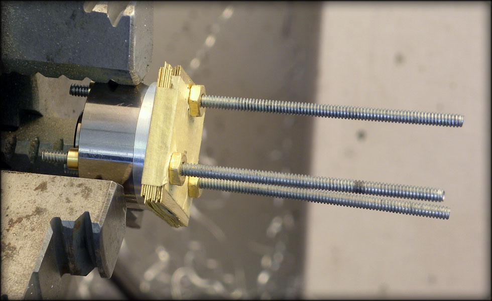
At this point, I decided to work on the radiator section, recreating that part from my graflex saber in this one, but at a much smaller scale. Previously, I had bolted the brass sheets to a block of wood and cut them down to size on the standup belt sander. This time I wanted an easier way to do it, so I cut, drilled and bolted the one inch square sheets to the top end of my crystal chamber, using the same support rods.

030.jpg


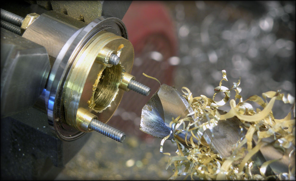
After using the lathe to turn them down to the right size, and dropping off a few that were bent, I was left with 6 or 7 that I liked, and then drilled them out hollow. This was much easier on the lathe than what I did previously.

031.jpg


Deciding to keep five of them, I spaced them out and sanded the sharp edges down on the outside and inside.

032.jpg


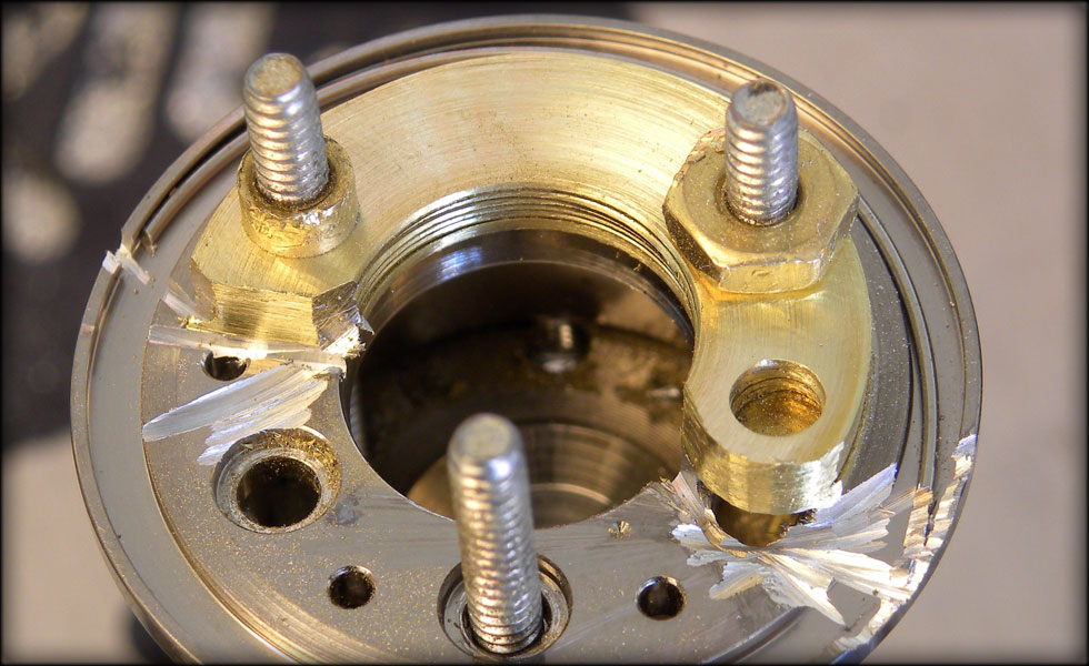
After spinning them to get nice radial sanded texture on the faces, I then used the dremel to cut away the section I didn't need, leaving the spot for the wire conduit on one side.

033.jpg


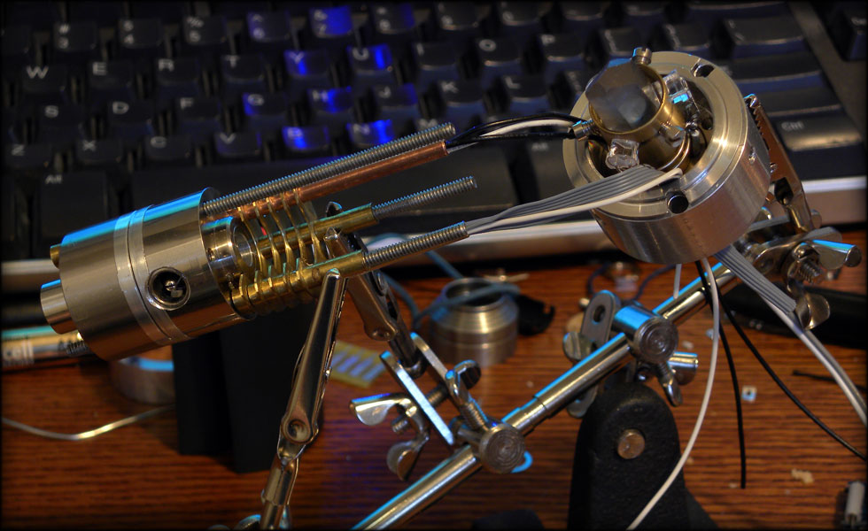
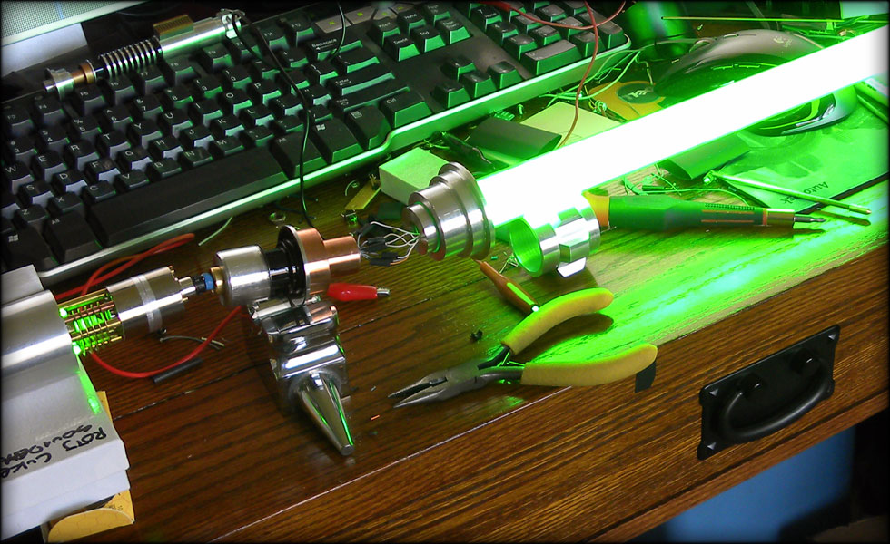
Here it is lit up, you can see the radiator sections below the crystal. I have yet to make the wire conduit section or hide the threaded rods.

034.jpg


I might go back and rewire my LEDs, I have a few revisions I'd like to do...

035.jpg
 
036.jpg


Remade the LED array, and lathed away some of the brass part of the mount. It's much cleaner now.

037.jpg


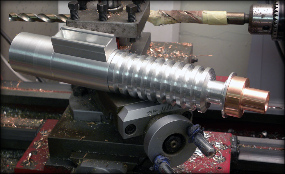
Tonight I spent a few hours machining part of the neck. This plug will fit into the forward grip, and be interchangeable between an emitter/neck with blade, and one without.

038.jpg


The slightly raised lip fits snug into a tiny bevel in the shoulder of the forward grip. A black setscrew will secure this, and be well hidden in the groove after it's painted. The copper section above this will cover the long tube.
 
039.jpg


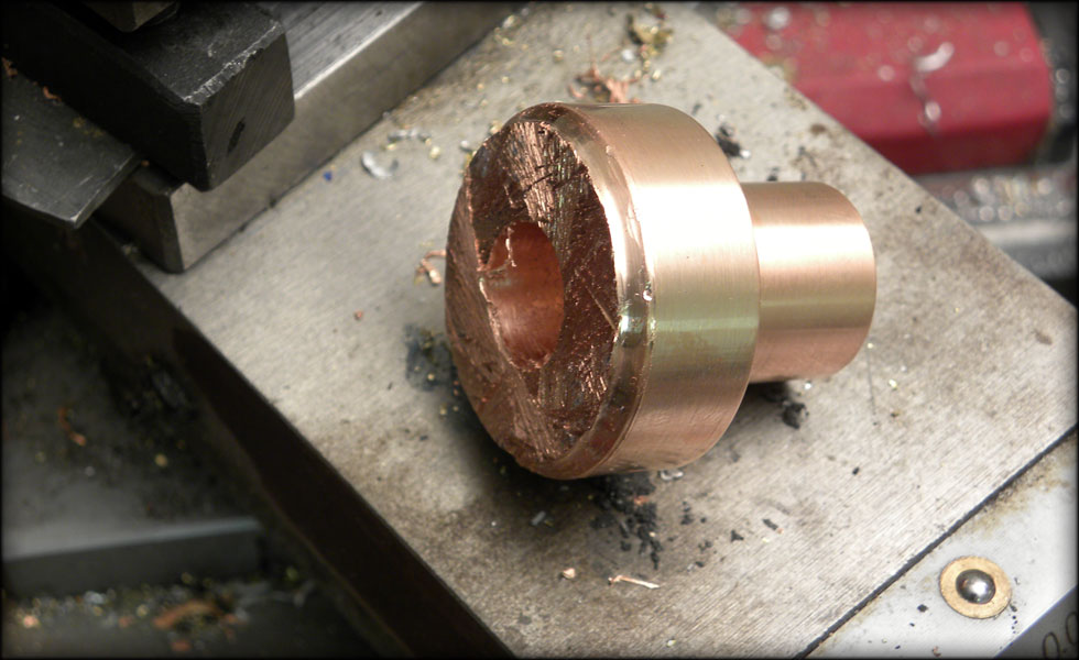
The copper collar that goes on the top section of the neck, I had to cut off with a hacksaw from the main stock, so I wasted as little copper as possible. Also, I hate this particular alloy of copper, as it's extremely difficult to machine. It work hardens pretty fast, and gets gummy.

040.jpg


After shaving off the hacksaw side, polishing and slipping it on to the neck

041.jpg


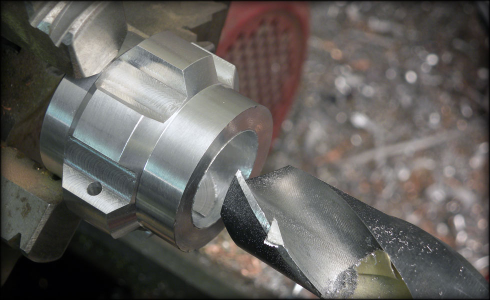
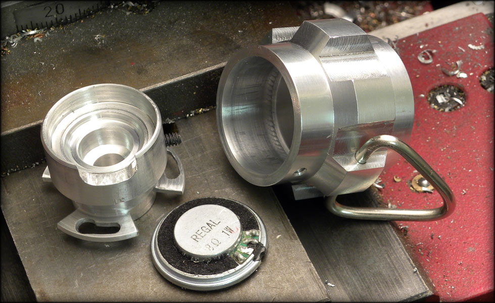
Now I need to hollow out the pommel for the speaker. To do this, I drilled a half inch pilot hole, then went in with my 7/8 bit. Slowly, because it's a bit dull, and it chatters some.

042.jpg


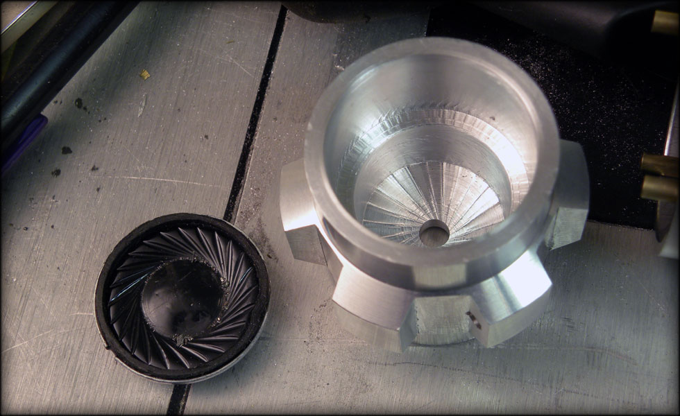
After boring out room for the speaker, the last bit of hollow section will be the resonance chamber. Hopefully it will sound ok, I can adjust a bit if I need to. Also, I drilled out the hole for the sound to escape.

043.jpg


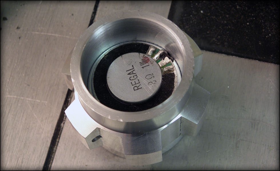
The speaker fits just fine. I'll machine a tube to go from the inside of the pommel, holding the speaker in, through into the inside of the main handle section. This will also serve as my base for the latch.

044.jpg


Here I am starting the emitter. I have a couple of emitters for reference, one from Rylo, one from the RPF, and I am sort of averaging those together for mine.

046.jpg


The bottom section machined, I'll drill this for a threaded 3/8 hollow rod, and flip it over to do the top section.

047.jpg


However, I couldn't resist putting the Rylo emitter on just for grins. It's really coming together!
 
048.jpg


Whew, got my emitter machined, and the pommel on there, still have a ways to go.

I got a lot done today, though it may not look like it...

049.jpg


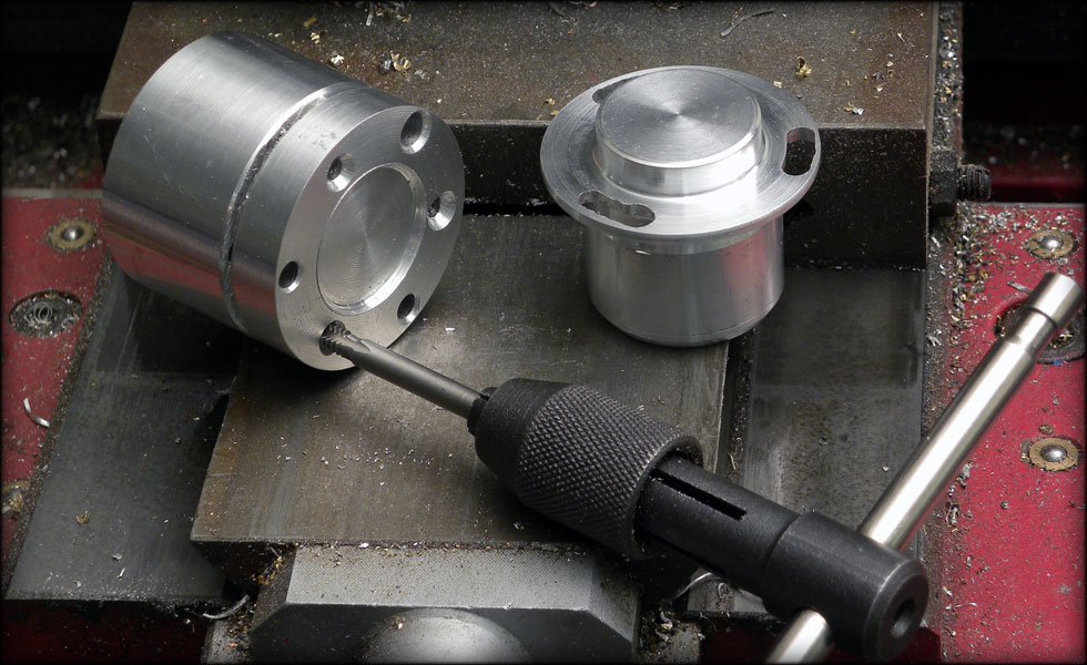
Set the recharge port today in the chamber top, and put three setscrews in to secure the harddrive motor case that is the base of my crystal chamber. That outer cylinder with the setscrews fits inside the main handle, and lets the rods go through to open and close the chamber.

050.jpg


This is the only place I could think to install the recharge port. Once the chamber is open, you'll be able to plug it in to charge the saber. I will probably shorten the chamber a bit, depending on how much length on my support rods I end up with.
 
053.jpg


Today's work involved the blade anchor plug that will serve as the inside of the emitter, holding the blade secure against the emitter shell. It was kind of dark in my office, so not so great a picture, let me turn on a light so you can see it better...

054.jpg


Oh yeah, we have ignition! The small bit of blade tube visible behind the emitter shell is very much like my Obi. I do this because it looks cool, and it gives me the most surface area inside the shell to anchor the blade.

055.jpg


It was so bright, it was messing with my camera, so the pic doesn't quite do it justice. I'll be finishing off the blade shortly, and beginning my wiring harnesses once I finish the two neck sections.
 
Heh, the wife says this one is TOO bright, blinding even. I might just dim it down a tad.

056.jpg


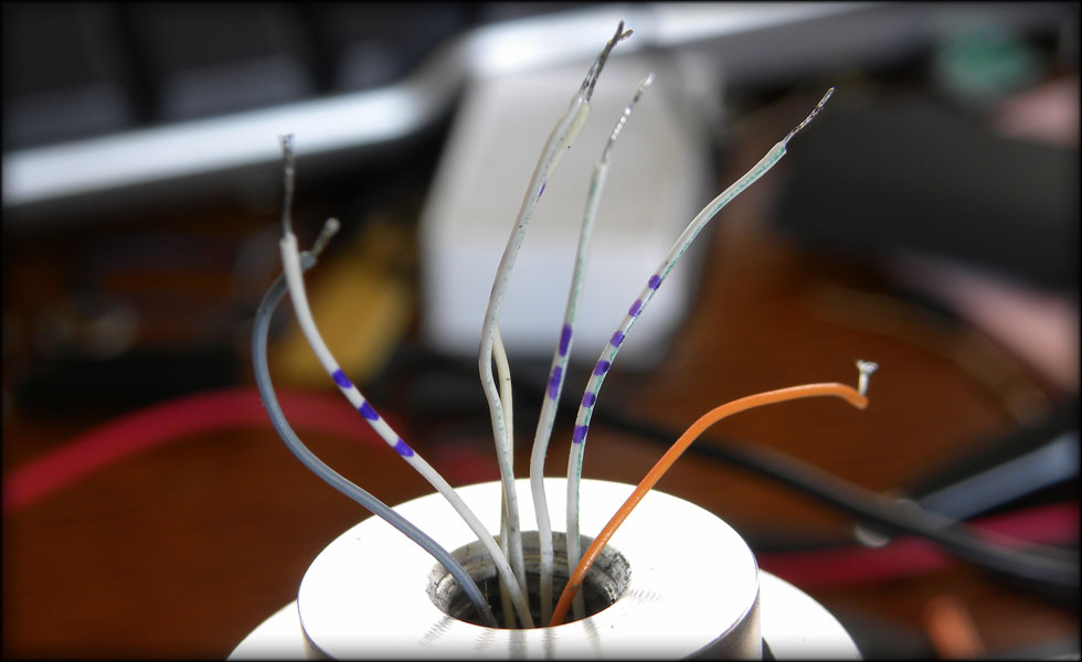
Getting the wiring all threaded through my tubing, I have three wires running through the copper to the recharge port. In the brass tube just behind the threaded support rod, I have a single white wire for the positive feed for the blade, surrounded by seven smaller ribbon cable wires to handle the grounding sections and the clash sensor. The wires for the crystal chamber are already threaded through the base.

057.jpg


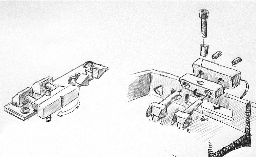
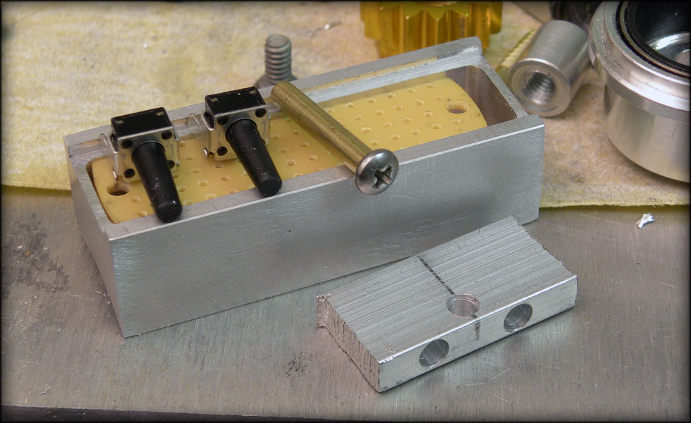
So here's what I am thinking for the control box. Aluminum blocks for the two switches, bolted and hinged as illustrated,

rear for activation, fore for clash trigger?

Also I have a trick up my sleeve for the two triangular LEDS. Not pictured here, the pololu latching switchboard also fits in there.
 
LOTS of work going on, almost not enough time to take pics...

almost.

059.jpg


LOTS of wiring going on this week. Carefully and meticulously measuring, trimming fitting all the wiring and electronic components into the handle. Lots of tedious back and forth, measure twice, cut once, solder, heatshrink, sew the wires into place, etc. Also, got both neck pieces machined, and painted, once the enamel is cured, I'll sand off what needs to be silver, and drill for the setscrews that secure each neck piece into the hilt.

060.jpg


The wiring of the blade is pretty small work, this is before heatshrinking the wires and stuffing them into the blade neck.

061.jpg


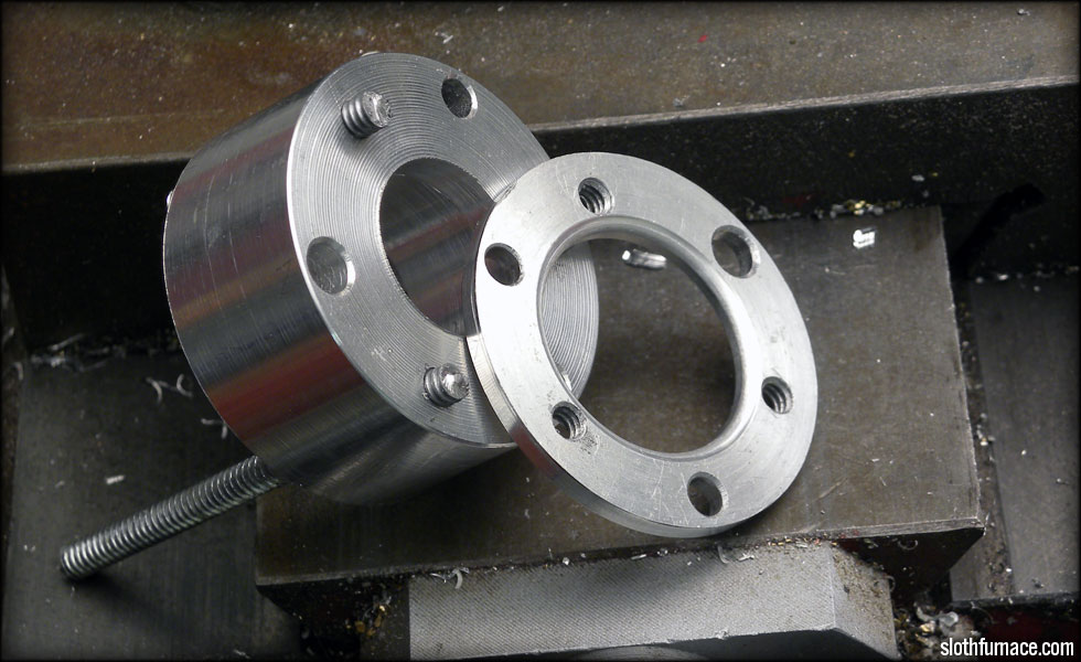
Here I am threading down through the template so all my bolt holes line up after I slice off my retainer plates.

062.jpg


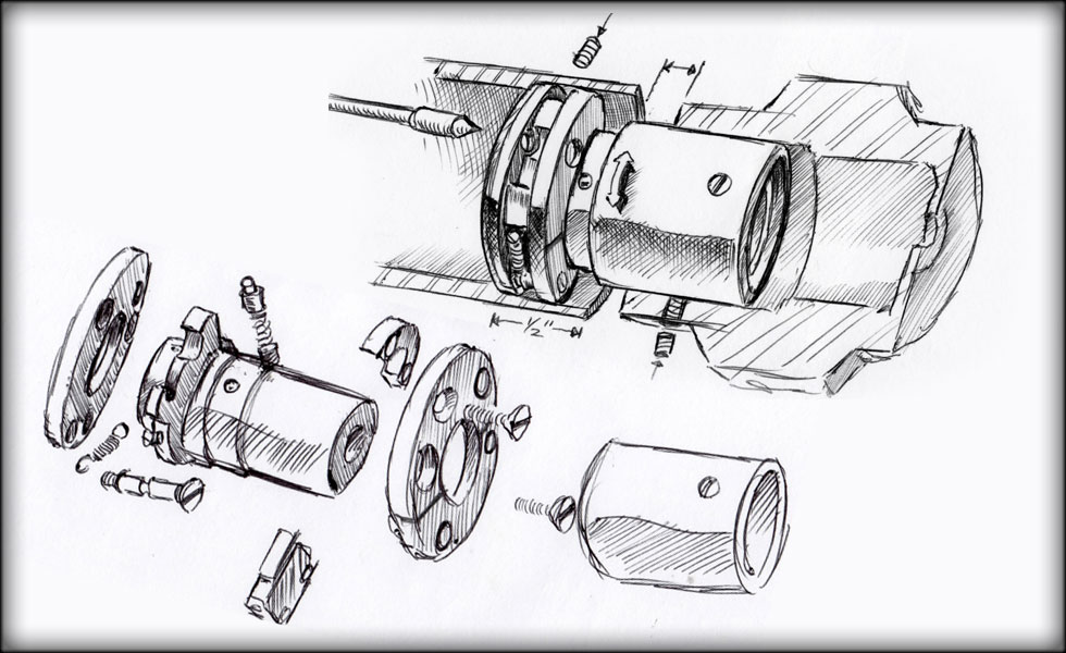
The template fits fine, and everything lines up. The latch twists clockwise to lock, letting the larger diameter plug pull against the slot to close it.

063.jpg


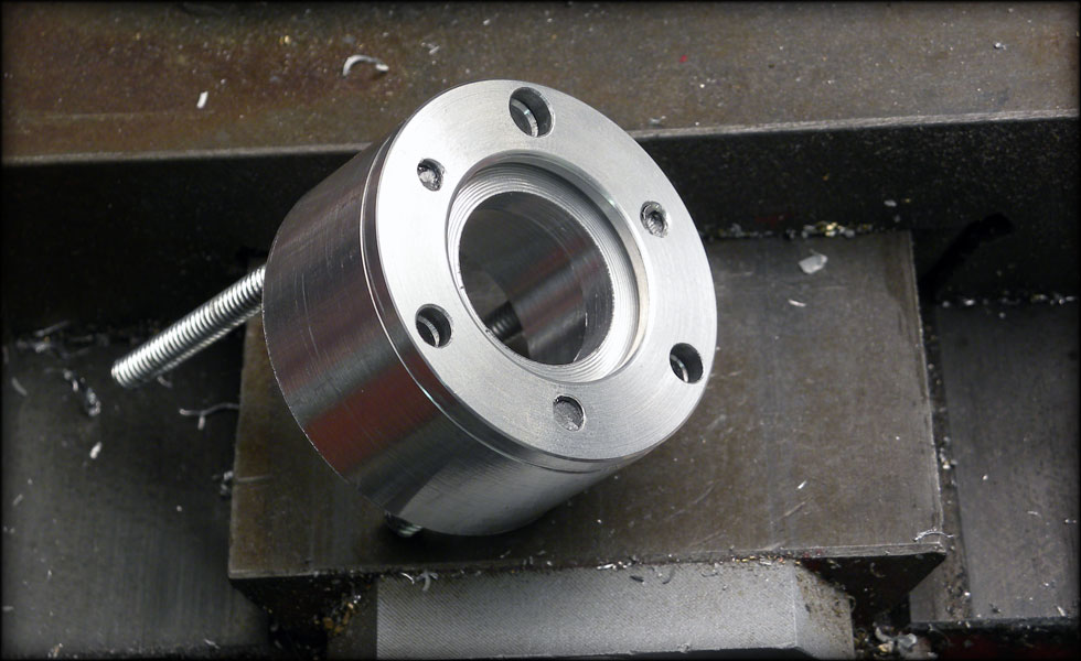
Here's the front retaining plate on the template after turning. I'll do the same for the back retainer plate.

064.jpg


Here you see the final front retainer plate.. This method works pretty well as long as the threads all line up vertically enough to keep the work plate snug and tight to the template. I used some masking tape between the two while turning on the lathe to get the final smooth finish.
 
061a.jpg


So here is what I am thinking for the pommel latch. I think I might lose some of the springwork in there, but for the most part it should go like this.

065.jpg


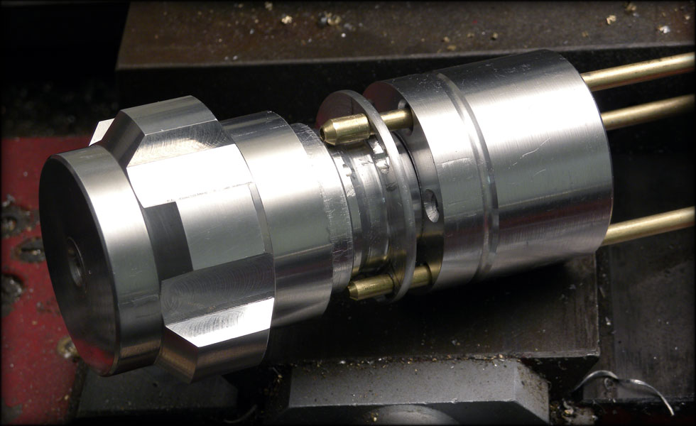
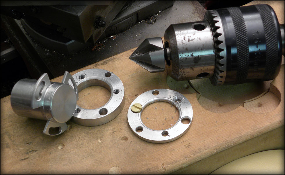
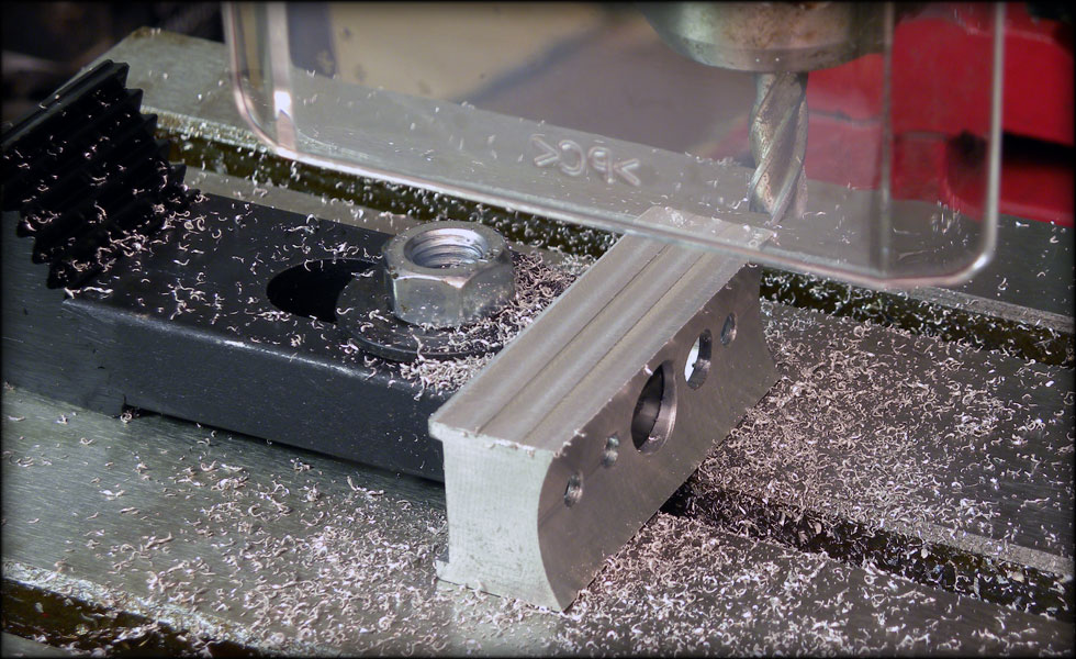
Well, this is as good a project as any to break in my new milling machine! Here I am milling out slots in the locking fins to allow the retainer bolts to go between fins.

066.jpg


Fin slots cut, now I countersink the screw holes so everything is flush. I do this by hand, as my drill press chatters when I attempt it, I just use the MT2 chuck with the countersink bit chucked in and press down and turn... .over and over again.

067.jpg


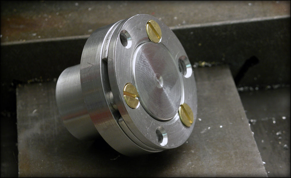
Screws countersunk, spacers machined, rod entry points countersunk so the support rods are fed into the lock instead of banging on the face of it.

068.jpg


Here it is locked, with the rods in it. I'll fine tune this a bit so that when it's all together, everything is flush and smooth.

069.jpg


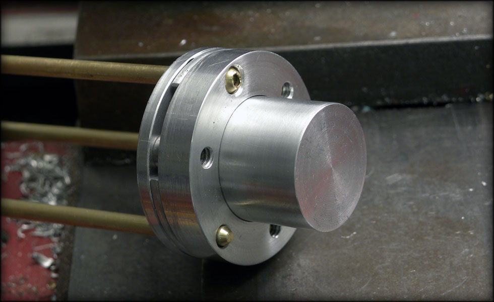
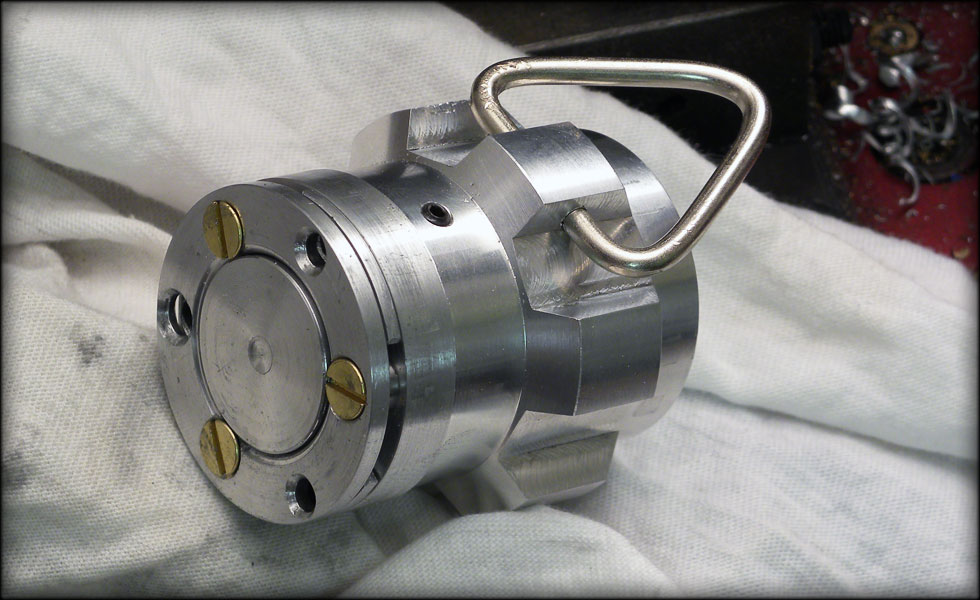
It works BEAUTIFULLY. A nice snap open, and closed. The rods move through the lock smoothly, and without rattle or wobble. I need to machine a collar to fit this protrusion and the pommel, and drill a hole through the lock for the speaker wire.
 
070.jpg


Here is the lock knob with the collar on. You can see the slot I milled out to allow for plenty of room for the speaker connections. I don't want to risk shorting here, as main power goes to the speaker.

071.jpg


The pommel attaches to the lock with a single 6-32 set screw going from the surface of the pommel through the collar, and into the lock knob.

072.jpg


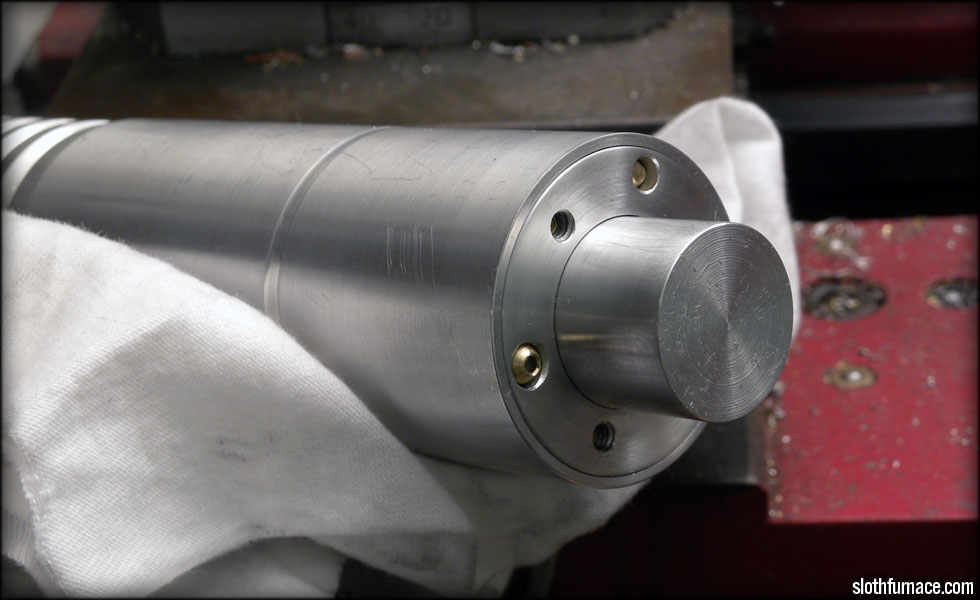
Painting the grip section, I taped off the back and front, and carefully spray painted with black enamel. Before painting I made sure to polish and wash with dish detergent to remove all dust, oil, etc.

073.jpg


Painted, allowing the grip enamel to cure before I shave off the outermost raised areas to reveal the aluminum beneath.
 
077.jpg


074.jpg


Now I need to start on the control box. First, I take a TCSS box and shave down the sides so there's no groove, then polish away the machine marks.

075.jpg


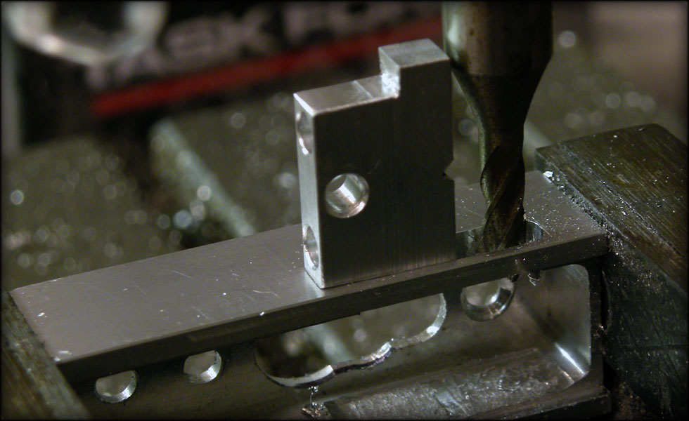
Then I take two long button 90 degree tactile switches, and measure out on a piece of aluminum stock where the tabs go, drill and testfit, then drill the pivot hole. The 4-40 screw will tighten this down against some brass tube, which will go into the pivot hole.
 
Last edited:
078.jpg


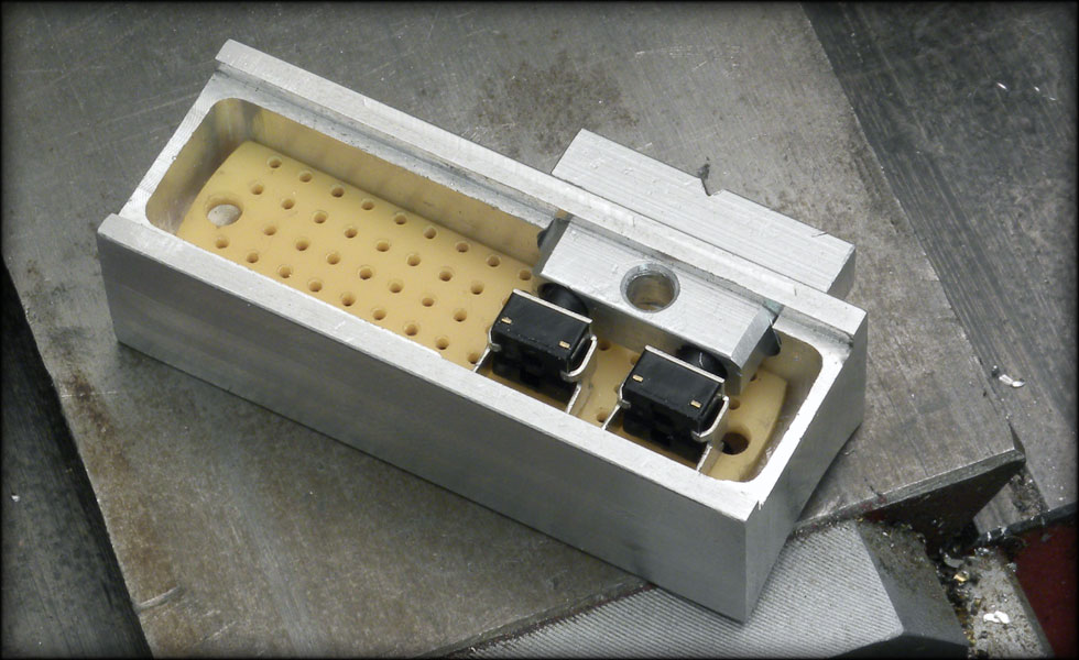
At this point I milled out the slot for the button. I took ever so slightly less off till the button barely fits in the slot.

080.jpg


Here's the button for test fit. When the screw is installed, it lets the button rotate JUST enough to activate either switch.

081.jpg


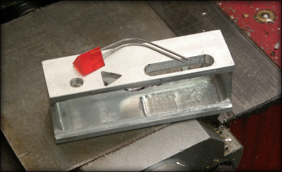
Here's the first triangular hold filed out. A small triangle file is needed for this kind of thing, and loads of elbow grease.

082.jpg


And here it is with both trianglar LEDs set for fit. I'll clean the box up a bit after I drill and tap for the two small brass screws that go underneath the LEDs.
 
Last edited:
Oh. I just now realized I could have just posted the final pics with a link to my site for the build log, but oh well.

If the thread is too bulky, I'll whittle it down. Sorry for any inconvenience.
 
Back
Top