You are using an out of date browser. It may not display this or other websites correctly.
You should upgrade or use an alternative browser.
You should upgrade or use an alternative browser.
Scratchbuilt Sten MkII - The Eagle Has Landed
- Thread starter Nick K
- Start date


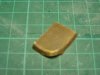
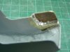
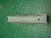
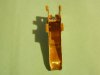
Next was making the trigger housing cover. After looking at the drawings I had, I decided to make this from some 1.5mm brass sheet I had. I traced the shape onto it then calculated the width and mirror imaged the opposite side. I then used sharp heavy duty scissors (yes, so long as they are sharp and heavy, they will work the same way as shears). I then folded it together and test fitted it to the housing to make sure it wouldn't spread. I then soldered it together with plenty of solder and even put some epoxy glue in there as well.
Attachments


Very cool!!! I always thought that would make a cool Star Wars blaster also.
blackhearted
New Member
I am working on a sterling on and off but other things seem to take over.
Sir..do you have the layout / blueprint / drawing for the sterling..can you share with us..that would be great.
Awesome progress
Thanks


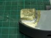
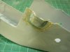
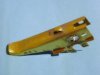
The next step was to make the Trigger Pin Cover, and this was made using a small piece of brass sheet and holding it in two pairs of pliers, after cutting to shape, and then bending over the round edge until it is almost 40deg. The edge to be soldered to the housing was then filed flat with a small file and test fitted to make sure that it sat nicely.
I then floaded the area with solder and ground it all smooth with my mini Dremel tool using a cut-off wheel.
I then floaded the area with solder and ground it all smooth with my mini Dremel tool using a cut-off wheel.
Attachments
Wow this is a really great build, thanks for sharing!

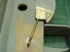
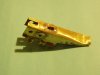
The Trigger. What can I say about the trigger. Only that I didn't take photos when I started making it. I copied the drawing I had, onto a piece of cardboard first so that I could get the dimensions right when it was cut out and folded. This was then scribed onto a piece of brass sheet and cut out with snips. This was gently folded in the correct places with a bit of tweaking, and then the hole for the trigger pin was drilled and a piece of brass rod was soldered into place. I then bent a small strip of brass to shape and this was soldered to the front to connect the trigger spring to.
Attachments
Last edited:

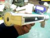
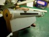
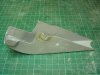
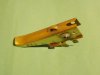
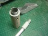
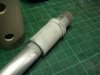
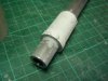
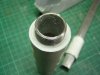
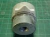
At the same time I started work on the Barrel and Sleeve. These were made from Alui tube and Galv plumbing fittings that could screw together.
Attachments

Last edited:


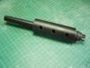


Here are some of the pics which didn't seem to come out the first time. (post #34) The galv pipe fittings were turned down on a lathe to fit inside the Pvc pipe I was using for the barrel sleeve and the receiver tube. A piece of Pvc tube was glued to the female pipe fitting and a front sight was fashioned from some styrene and glued on. The other pipe fitting was built up to the correct diameter so it would fit in the barrel sleeve and then glued in place and filer was used to tidy it up.


Attachments
Similar threads
- Replies
- 1
- Views
- 769
- Replies
- 6
- Views
- 371
- Replies
- 0
- Views
- 1,145
- Replies
- 0
- Views
- 754
- Replies
- 6
- Views
- 1,586