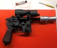
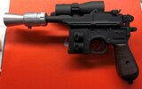
ROTJ Han Solo DL44 (Bunker Version) Build

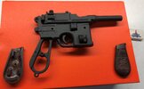
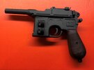
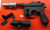
I just put the final coats of paint on some of the parts, including the Mauser and Flash hider:
IMG_2033.JPG

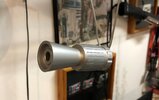
This is the first time I've painted a Derlin flash hider and I have to admit that I'm really impressed with the results. It's easy to tell how this could be taken as a machined, aluminum part:

IMG_2034.JPG

And since Derlin is much lighter than aluminum, it's the perfect material for a prop.

I'm going to give these parts at least 2 or 3 days to dry before beginning final assembly.
 
The screws on the piston halves were topped with a circular piece of tape painted black. In some close ups, you can see that the diamater of the circular tape is slightly smaller than the head of the screw. On the current props, these tape pieces have fallen off some of the screws.


I noticed in the newer reference photo that the slotted bolt is deeper in the flash hider than I had realized, so I counter sink the hole a little more.
Before moving forward with the piston half installation, I need to expand the piston half bolt areas using a 1/4" end mill. Here's a before pic:
View attachment 1366093

The expanded area is toward the the "grill" area of the piston half. I think the reasoning behind it was to get enough room for the 1/4" diameter bolts that were used. With the pistons machined, I use the reference photos to get the bump placed in the correct spot. Although the bump is placed different on both Bunker blasters, after looking at the MoM blaster, I noticed a pattern: All the bumps are centered within the mount area, so this is how I place the bump:


View attachment 1366094

I'm not working with a rubber bump, so I use my belt sander to create a step at the bottom of the bolt so it sits flat on the Mauser:

View attachment 1366097

I use some contact cement to attach the bump and super glue to attach the piston half. I use 220 grit to sand the areas on Mauser where the parts will sit, and then the parts before placing them:

View attachment 1366099

I noticed in the newer reference photo that the Phillips head bolt appears to be completely flat. It's very difficult to tell if the bolts are flat on the left side of the blaster, but since all of the bolts used on the blaster were counter-sunk into place, it only seems to make sense that this is how it was done on the left side. Here's the newer reference for the right side. Notice that the bolt for the piston half is completely covered in dust:

View attachment 1366101

And the left side:
View attachment 1366102

Both parts are drilled, tapped and counter sunk. Here's the Mauser with the bolts installed:
View attachment 1366107
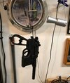
 
The screws on the piston halves were topped with a circular piece of tape painted black. In some close ups, you can see that the diamater of the circular tape is slightly smaller than the head of the screw. On the current props, these tape pieces have fallen off some of the screws.
Interesting. That explains why the bolt can’t be seen on the right side. At least in the newer photo. My first thought was that the bolt was covered in dust, but tape or a plastic cap would make sense.
 
I found the photo reference. It’s from Jason debord’s site on an article regarding the auction sale of that particular blaster. Zooming in on the bottom Phillips screw indicates that a small circular piece of tape went over the screws. Perhaps the top screw’s tape peeled off?

2B132089-F303-459F-998B-30E8DF3FF6B4.jpeg


Interesting. That explains why the bolt can’t be seen on the right side. At least in the newer photo. My first thought was that the bolt was covered in dust, but tape or a plastic cap would make sense.
 
Last edited:
lol

and the screws look to me to be pan head or dome headed, for research's sake. I also didn't notice they beveled the other end of the pistons!

Great looking blaster Vince
 
:lol

Unfortunately, some blasters, like the Hoth version have both screws and bolts (for the scope), but it looks like this version just has screws. :p

I was going to do a final assembly last night, but there's still some painting that needs to be done on the left side.
The right side looks good, though:

IMG_2080.JPG
 
The left side is done. I had forgotten to clean one of the screws before installing it, so the paint wouldn't adhere to it and part of the piston half, so both parts had to be cleaned off and repainted.
The grips get installed first and the front of the barrel is sanded slightly before applying a little contact cement within the flash hider:

IMG_2111.JPG

The flash hider is installed with both screws. I left the screws unpainted because I thought they looked better.
The painters tape is removed from the lens area of the scope and the back ring is pre-installed on the mount to make that part of the installation easier:

IMG_2112.JPG

The spacers were machined to fit, so those don't need to be glued to the Mauser. The mount is simply attached with the two screws, along with the scope and viola:

IMG_2113.JPG

Left side:

IMG_2114.JPG

Easy assembly, but practically all of the parts need to be machined because that's how the original was built.
Special thanks goes out to every one who contributed reference photos and info. ;)
 
This thread is more than 3 years old.

Your message may be considered spam for the following reasons:

  1. This thread hasn't been active in some time. A new post in this thread might not contribute constructively to this discussion after so long.
If you wish to reply despite these issues, check the box below before replying.
Be aware that malicious compliance may result in more severe penalties.
Back
Top