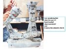
Revell At-At WIP... finishing up!

My cam and pin operates perfectly but once the limiter was attached it fowled on the leg when moved into the knee up position... it was only just short of full extension and not concerning for this build but I would like others to be aware of it.

So ... what you're saying is ... the pin in the limiter should be slightly higher up? For those of us using your thread as a guide-line to alter/upgrade our Revell AT-AT ... it's crucial for us to at least know to the millimeter in order to achieve ... perfection!

I.e. How did you attach the legs to the hips?

Chaïm
 
Last edited:
I'd say these legs are looking great! Nice adaption for the bolt heads. All these little details really add up.

Thanks! I figure that ( without scrutinising) if I can look at a studio pic or screenshot and then to the model and the details basically there I'm happy for this build. I feel like it's starting to come together now.

So ... what you're saying is ... the pin in the limiter should be slightly higher up? For those of us using your thread as a guide-line to alter/upgrade our Revell AT-AT ... it's crucial for us to at least know to the millimeter in order to achieve ... perfection!

I.e. How did you attach the legs to the hips?

Chaïm

It seems the pin limiter should be slightly higher up but the pin on the leg can't be in too far either.
Bare with me over the next week and I will cut another dummy leg and mechanism and nut out the locations. Once done I'll post the file up of the pieces and I will run through how I assembled everything.
You can see the screw through the back of the hip to the leg. It simply screws through into the cam on the leg.

Great work!
Thanks!

Cheers,
Josh
 
Hey Josh, didn't start the new project thread we talked about yet where this should probably go but this is still related to this thread as the picture below might help with pin placement distance ratios. These are more accurate shapes and what I will be printing from.

Almost have a full upper leg with linked pistons and motion drivers to the knee fly wheel worked up with pin placements and ranges of motion. The positions of the completed parts (except the pistons) as I move them through the motions seem to match what I see on the screen pretty well so far but man there are a lot of dependencies with the pieces. Using solid linkages to drive everything requires making lots of little adjustments to pack everything in the leg.

It has occurred to me that driving the pistons with a strap and elastic was actually a pretty genius and simple way of doing it. To capture the full range of motion I see on the screen the piston fly wheel seems to need to rotate more than the fixed range of motion a direct hard link would provide. By putting a semi-rigid strap across the small center post to create rolling friction and an elastic over the strap to hold it in place, a very long length of travel is achieved and the elastic can stretch to accommodate the changing distance between the anchor points without the strap slipping on the rotating post until the limits of piston travel are reached.
04_pic.JPG
Currently trying to simulate the strap and elastic with a curved rack and pinion type of drive but on a larger center diameter. It will have to have sections of no teeth at each end to provide the slip action I think is there in the models action and a pivoting constraint (not shown) to keep it in contact with the pinion. It is on the back side of the can so as to not interfere with the pistons. Not a straight forward solution and might not work in the end. Here is what I have so far. The piston driver is not in the right place yet and the cam angles need some adjustment.

Leg Motion Mapping.jpg


The more I work on this the more impressed I am with what the model builders created.
 
Hey Josh, didn't start the new project thread we talked about yet where this should probably go but this is still related to this thread as the picture below might help with pin placement distance ratios. These are more accurate shapes and what I will be printing from.

Almost have a full upper leg with linked pistons and motion drivers to the knee fly wheel worked up with pin placements and ranges of motion. The positions of the completed parts (except the pistons) as I move them through the motions seem to match what I see on the screen pretty well so far but man there are a lot of dependencies with the pieces. Using solid linkages to drive everything requires making lots of little adjustments to pack everything in the leg.

It has occurred to me that driving the pistons with a strap and elastic was actually a pretty genius and simple way of doing it. To capture the full range of motion I see on the screen the piston fly wheel seems to need to rotate more than the fixed range of motion a direct hard link would provide. By putting a semi-rigid strap across the small center post to create rolling friction and an elastic over the strap to hold it in place, a very long length of travel is achieved and the elastic can stretch to accommodate the changing distance between the anchor points without the strap slipping on the rotating post until the limits of piston travel are reached.
View attachment 1462740
Currently trying to simulate the strap and elastic with a curved rack and pinion type of drive but on a larger center diameter. It will have to have sections of no teeth at each end to provide the slip action I think is there in the models action and a pivoting constraint (not shown) to keep it in contact with the pinion. It is on the back side of the can so as to not interfere with the pistons. Not a straight forward solution and might not work in the end. Here is what I have so far. The piston driver is not in the right place yet and the cam angles need some adjustment.

View attachment 1462739

The more I work on this the more impressed I am with what the model builders created.


Wow that's some fantastic work!
And not going to tell a lie a lot to get your head around haha.

But the photos are great and I will overlay them in Corel to see where my pins lay in comparison.

There's a fair bit of compromise in lasering the parts as if your too close to the edge of the hip or cam disc the parts aren't solid so really the cam disc half moon slot and the hip slot could benefit by being a little longer. My leg extension pin does need to be a tad higher.. like maybe 2mm.
But the positive is I can cut a dummy leg, hip etc off your design and pin it together and check that basic outer cam and leg extension to hip movement all works easy peasy.
Even moving foward to the piston cam and pieces we can cut those easily and make a working model... even if we don't have all the components thicknesses correct we can demonstrate the mechanics if you like, save you some hours 3d printing.

Cheers,
Josh
Yeah, it is a lot to wrap your head around. ...and I posted the readers digest version. :p Skipped what I'm doing for the knee flywheel.

Have at it lasering out all the profiles. Alternative methods of construction was a target of the project and concept testing of the motions with the different methods as we go along might teach us a lot. I could import the 3D files and after some line removal send you a native Corel file to cut from. That way future mods can be passed back and forth and be in scale to what we are working on. What Corel version are you using?

My printers have a tolerance of 0.075mm on average but I design for 0.1mm. Might have to use a different tolerance allowance for a laser. Once we know what we are dealing with it allows for interchangeable parts between the two production methods.


Im on Corel 15. A little older now but works well enough for line drawing for a laser. Becomes a problem though when people send me artwork on newer versions and I have to send them onto my sis, who is a commercial artist, to change them to the older version for me.


The lasers tolerance is 0.05 . And surprisingly very accurate for being on belts and not steppers.

If ( long term) Im going to look at 3d printers what should I be looking at?

It will be quite exciting to produce a fully functioning leg!

Cheers,
Josh
 
Last edited:
I don't know if this can help, but this is how I got the articulation of the different moving parts on the legs.
One tip: don't make the gears out of plastic :(. If you want them to be durable, make them in aluminum or brass.

Cheers,
Rafa

My old thread: Fully improved AT-AT (MPC-ERTL)

Fantastic work on that solution Rafa thank you for sharing. It does help with some ideas. Really like your knee fly wheel solution. And a great looking result on your MPC AT-AT that you applied them to. Really like your other work as well. That Snow Speeder looks great.
 
Im on Corel 15. A little older now but works well enough for line drawing for a laser. Becomes a problem though when people send me artwork on newer versions and I have to send them onto my sis, who is a commercial artist, to change them to the older version for me.


The lasers tolerance is 0.05 . And surprisingly very accurate for being on belts and not steppers.

If ( long term) Im going to look at 3d printers what should I be looking at?

It will be quite exciting to produce a fully functioning leg!

Cheers,
Josh
I have Corel 19 so I can accept your files and export back out as 15 for you.

The laser tolerance is the same as my tightest tolerance printers so profile designs with a 0.1mm tolerance clearance will work for both methods.

As for printers I built my own and highly recommend them :p but Creality Ender Pro series makes a very good one if you buy commercially. A 10x10 bed with a 10-14" Z is a good minimum volume for what I do. Resin SLA does a great job on fine detail and organic shapes. FDM does very well for stronger structural parts and general shape. I can get really good detail on my FDM's with 0.05mm layers and a 0.3 or 0.2mm nozzle but it takes time. Generally I use a 0.4mm nozzle and 0.1mm layer height. I'd look for something with at least those capabilities.
 
I don't know if this can help, but this is how I got the articulation of the different moving parts on the legs.
One tip: don't make the gears out of plastic :(. If you want them to be durable, make them in aluminum or brass.

Cheers,
Rafa

My old thread: Fully improved AT-AT (MPC-ERTL)


Thanks for adding to our journey! a clever idea for consistent articulation.

You have given me some research to do on printers now Hagoth. And your brief description here cleared up quite a few questions for me regarding Resin and FDM, thank you.

Quick update before leaving for work.
I had to do something with the shock absorber, the Revell is too thin.
Studio
Cp47Yle.jpg


I cut down either end of the Revell shock absorber, drilled out the big end and slotted in the skinny end to make the leg to shock pivot. This end is now turned around from it's intended way of assembley, so the new base in the leg and the key that would have gone in the leg is now going in the shock.
I got some styrene rod and fitted it into some brass tube I had here. I slightly squashed the base of the brass tube so it holds the styrene rod but I can still move the rod in or out. a wipe of filler around the top.
No Rembrandt but looks the part for a static model.
1bBxUwM.jpg

mMAs4VS.jpg

kzc8oeP.jpg

jwHRzwD.jpg


A quick throw together, nothing adjusted or in place yet.

nUKdJp8.jpg


And these arrived!
1KJibZm.jpg

CpzieXk.jpg


So I can finish up on the guns for the head. I will build the speeder and move to paint all together I think.

And for people to copy, heres a close up of the Flakvierling armour plate for the rear of the walker
rKel12I.jpg


Cheers,
Josh
 
With all these amazing mechanical concepts flying around I thought I'd share this utter nightmare I embarked on a few years back. I was trying to make a walking Revell AT-AT either through a series of cogs or through servo motors. I even got in contact with Adriano Kenobi, who created the amazing walking AT-AT that can be seen on YouTube, but alas, he wasn't for sharing his idea. The only thing he did mention is that he used one motor and a cam system.

Working out the walk cycle was pretty straightforward, but trying to hide all of the components so it could fit into the form factor of the legs was sheer lunacy.

at 2:53 is a servo idea that could actually work and remain hidden.


And here is a stop motion test on the Bandai!


Hope this doesn't derail the thread too much. Perhaps this will be a retirement project in 25-30 years time?

Doesn't derail the thread at all and more than happy for people to add as they feel inspired to. We all learn that way.

A shame to hear Adriano Kenobi not sharing much with you, I mean whats to benefit by keeping that knowledge to yourself? I always figure no matter how great you think you are there will always be someone else to wipe the floor with your achievements so may as well be humble in the beginning.

Did you film the Bandai stop motion?? Thats AMAZING!! I would love to know how long it took to get those 3 seconds.

Cheers,
Josh
Yeah, I held the model in a clamp and did it that way - probably took about an hour to do. The main issue is that because the walk is so slow you end up moving bits about 1mm at a time and you do get parts slipping a bit. Still really fun to do (apart from moving the wrong leg at the end)

If anyone is interested, the program I was using for the physics stuff is Algodoo - it is completely free, and I have just re-downloaded it. Extremely quick and easy to use. All my files are intact so if any one wanted some to play around with you would be welcome to them.
 
Im starting on the side guns, so one cut down 20mm gun above a full length one. Would love to know what they retained the lower gun in. But thinking can heavily modify the Revell guns to fit the Tamiya ones.

Analyzer do you have close ups of the side guns on the Bandai model by any chance?

Cheers,
Josh

I'll get some pics later today
 
With all these amazing mechanical concepts flying around I thought I'd share this utter nightmare I embarked on a few years back. I was trying to make a walking Revell AT-AT either through a series of cogs or through servo motors. I even got in contact with Adriano Kenobi, who created the amazing walking AT-AT that can be seen on YouTube, but alas, he wasn't for sharing his idea. The only thing he did mention is that he used one motor and a cam system.

Working out the walk cycle was pretty straightforward, but trying to hide all of the components so it could fit into the form factor of the legs was sheer lunacy.

at 2:53 is a servo idea that could actually work and remain hidden.


And here is a stop motion test on the Bandai!


Hope this doesn't derail the thread too much. Perhaps this will be a retirement project in 25-30 years time?
This kind of input is great!

Once we figure out how to duplicate the motion of all the parts on the studio models in a repeatable fashion, at least well enough to potentially do a stop motion sequence that matches as closely as possible to what we see on screen, I've also had thoughts of how to make it walk with motors. Adriano has demonstrated what is possible so the argument that it can't be done is a moot point to me. Now to add in all the spinning flywheels, moving pistons, and shock absorbing feet and take the concept to the next level.

Yeah, I've gone round the bend with this lunacy stuff. At least it is sheer so I can see through it... well enough at any rate to I see we have some company. :p :cool:
 
Sorry it took so long, been super busy with work, but here is pictures of the Bandai part

Let me know if you need different view or angles or if you want me to try getting a more in focus/better quality shot for any of them ( I just quickly set up, so no tripod and autofocus left some things a bit fuzzy)

IMG_5778.JPG

IMG_5784.JPG

IMG_5779.JPG
IMG_5782.JPG

IMG_5781 (2).JPG
 

Your message may be considered spam for the following reasons:

If you wish to reply despite these issues, check the box below before replying.
Be aware that malicious compliance may result in more severe penalties.
Back
Top