You are using an out of date browser. It may not display this or other websites correctly.
You should upgrade or use an alternative browser.
You should upgrade or use an alternative browser.
"Reddish Jammer" Y-Wing Build
- Thread starter Studio Kitbash
- Start date
-
- Tags
- star wars a new hope
Today is my 50th birthday, and here is my gift to myself (and you, if you're interested in a virtual nurnie party to celebrate)...
The original 1974 boxing, of the Revell 1/570 HMS King George V ("Battleship That Sank the Bismarck")

or you could get this other one instead, the re-issued model, new in 1975 (and likely what the ILM guys got from Sentai Distributors) which is the exact same model but with different markings, The Revell 1/570 HMS Prince of Wales ("British Battlewagon") with a flying Walrus on the upper left of the original and awesome box art. (The new boxings are crappy art pieces, imho, but they still have the piece you want)

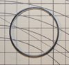
But in both boxings, you're looking for part #64. This is the "Mainmast" piece, and is the confirmed donor for one of the long-sought after "mystery greeblies" from the wing subassembly, of which there are four on each/every Y-Wing. (So this piece shows up 32 times on the 8 original Y-Wings that were built for the original 1977 Star Wars film)

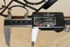
From left to right on the metric ruler: 1.) Way Too Small, 2.) Almost But Not Quite, and then finally, 3.) Aahhh, Just Right. The far right nurnie is 3.+mm wide at the top, just slightly larger in width than the circular Heinkel He-177 reticle nurnie. When you modify it, you'll need to not only cut it off the top "Mainmast" piece at just above the next cross-spar, but also cut off the little center nib on top, which does not exist on the center piece Tamiya 1/700 (Part #C36) version of the nurnie.
Here it is on the resin-cast subassembly.

And here it is on the full original nurnies subassembly, soon to be recast in resin.

Why was this one so hard to find? Two reasons: 1.) Because it was hiding in plain sight as a tiny section of a larger piece, and 2. )Because after finding the right shape in the Tamiya 1/700 Prince of Wales kit, but realizing it was too small, I spent all my energy looking for it in 1/600 scale, not knowing that there was such a thing as 1/570 scale (I am a plane builder, and have never been a ship builder). THAT's when it was helpful to have the Revell '75-76 Catalog and the '76-77 catalog on hand to cross check the available kits. And that's where I discovered, oh hey, there's this one kit in 1/570 scale that I've never looked at...
One fun little piece of historical trivia: the Y-Wing was among the first models built, possibly as early as December 1975. How late was it built? Well, the 1975 boxing of the HMS Prince of Wales includes this flyer for a Sweepstakes Entry form with the headline, “Revell Soars Into 1976 with Wing-n-Wheel Sweepstakes” Grand Prize: A Cessna 150 Commuter Airplane!" The deadline for the entry form is May 31, 1976, so while this does not guarantee or prove anything conclusively, it at least increases the plausibility that the model was purchased, if not in 1975, then at least within the first five months of 1976.
Happy Birthday y'all.


The original 1974 boxing, of the Revell 1/570 HMS King George V ("Battleship That Sank the Bismarck")
or you could get this other one instead, the re-issued model, new in 1975 (and likely what the ILM guys got from Sentai Distributors) which is the exact same model but with different markings, The Revell 1/570 HMS Prince of Wales ("British Battlewagon") with a flying Walrus on the upper left of the original and awesome box art. (The new boxings are crappy art pieces, imho, but they still have the piece you want)
But in both boxings, you're looking for part #64. This is the "Mainmast" piece, and is the confirmed donor for one of the long-sought after "mystery greeblies" from the wing subassembly, of which there are four on each/every Y-Wing. (So this piece shows up 32 times on the 8 original Y-Wings that were built for the original 1977 Star Wars film)
From left to right on the metric ruler: 1.) Way Too Small, 2.) Almost But Not Quite, and then finally, 3.) Aahhh, Just Right. The far right nurnie is 3.+mm wide at the top, just slightly larger in width than the circular Heinkel He-177 reticle nurnie. When you modify it, you'll need to not only cut it off the top "Mainmast" piece at just above the next cross-spar, but also cut off the little center nib on top, which does not exist on the center piece Tamiya 1/700 (Part #C36) version of the nurnie.
Here it is on the resin-cast subassembly.
And here it is on the full original nurnies subassembly, soon to be recast in resin.
Why was this one so hard to find? Two reasons: 1.) Because it was hiding in plain sight as a tiny section of a larger piece, and 2. )Because after finding the right shape in the Tamiya 1/700 Prince of Wales kit, but realizing it was too small, I spent all my energy looking for it in 1/600 scale, not knowing that there was such a thing as 1/570 scale (I am a plane builder, and have never been a ship builder). THAT's when it was helpful to have the Revell '75-76 Catalog and the '76-77 catalog on hand to cross check the available kits. And that's where I discovered, oh hey, there's this one kit in 1/570 scale that I've never looked at...
One fun little piece of historical trivia: the Y-Wing was among the first models built, possibly as early as December 1975. How late was it built? Well, the 1975 boxing of the HMS Prince of Wales includes this flyer for a Sweepstakes Entry form with the headline, “Revell Soars Into 1976 with Wing-n-Wheel Sweepstakes” Grand Prize: A Cessna 150 Commuter Airplane!" The deadline for the entry form is May 31, 1976, so while this does not guarantee or prove anything conclusively, it at least increases the plausibility that the model was purchased, if not in 1975, then at least within the first five months of 1976.
Happy Birthday y'all.
A very Happy Birthday. I'm in absolute awe of your focus in finding these details.
Read, Nice work on the conversion of struts to the nacelle clips. The solution you propose is certainly possible, though not conclusive. A couple of things to consider, the sides sloping away from the two tiny rivets are indeed sloped outwards, not parallel or an optical illusion of shadows. See the attached images of the same detail parts used in the 5 foot Millennium Falcon engine dampers. You can definitely see that they are sloped. Your solution could still be valid, it's just that a bunch of additional filing would be needed to taper the sides, but still doable.
Your reasoning as to why the two rivets are different sizes, being cut imprecisely from another part is a valid explanation.
Another interesting thing seen in the Falcon dampers is that the dimples are different depths on different castings! This would simply never occur with multiple resin parts cast from the same mold. However, it could very well have occurred if the parts were injection molded and we know that they had a small single shot injection molder in the model shop and used if for a few pieces.
In the end, we may never know, but it sure is fun to speculate!
Attachments
Hammer3246
Sr Member
I guess its possible that several were constructed your way, then cast.
Dave,
Thanks for your eagle-eyed feedback; much appreciated! The sloped-outward-ness of the nurnie, thanks to the images you provided, settles it once and for all: the inner-wall to outer-wall sections are in perfect relationship to each other, having identical distance between the "low" section and the "high" section -- this is the same relationship found on the nurnie itself. What THIS means, conclusively, is that they were assembled using a cut-off piece as a "shim" to go on the underside of the two round portions, so that the entire assembly would "fill" the same angled opening in the Kettenkrad nurnie as much as possible, using as little putty as possible (i.e., maximizing styrene-to-styrene bonding ability with regular model glue). The significant claim remains: there is NO missing nurnie; there is simply a complex initial sequence to the making of the master subassembly.
As for reproduction, I like your notion that these may have been mastered, and then injection molded using the machine they had, accounting for the different-sized divots in various versions of the nurnie.
Once I acquire one more Bandai Messerschmitt, I'll demonstrate the technique again in a step-by-step manner, in order to reproduce a master that has these sloped-outward sides. My reference photographs made it look like it was an optical illusion/trick of the light/shadow effect, so I'm delighted to have this cleared up with even better reference images.
Where is that center inner ring from? Was it kit-bashed? Or machine-tooled?

I believe it was kit-bashed. I believe this for a couple of reasons:
1. Because whenever ILM could find the shape and size they were looking for in a model kit, it saved them time and money on machine-tooling.
2. Because on the actual model (unlike the DaveG perfectly-fitting 3D prints shown above), the center ring is slightly "off" of being perfectly flush with the inside of the Sealab Crane Part #59 double-sided/mirrored nurnie, as seen in the detail picture below of the Alan Ladd rear vectral

3. Because I believe I have found the part.
4. And because this part is perfectly "mismatched" to the Sealab nurnie in the same way the original was.
Here is the part on top of DaveG's 3D file printed equivalent:

Here is DaveG's 3D-file printed ring piece on top of the kit bashed part

Here are the two parts side by side.

Here is the part fitting "perfectly" inside DaveG's 3D vertical rear vectral fin, overhead view.

Here is the part fitting "perfectly" inside DaveG's 3D vertical rear vectral fin, side view.

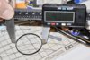
Here are the measurements of the part, roughly 38mm inner diameter and 40mm outer diameter, but not "exactly" these numbers:

Inner diameter 38.62 (but don't take this as gospel, as I'm measuring a flexible part and each time I do it I get a different number, so even this is a "pretty close" guesstimation)
Here is the outside diameter:

Outer diameter is 40.54 (but again, don't take this number as gospel). The key is that it is pretty much 38mm on the inside and 40mm on the outside, with roughly 1/4 a milimeter (0.25mm) of wiggle room (i.e., the limitations of either my tool or my measuring abilities)
Here it is fitting inside (but just barely) into DaveG's 3D-printed horizontal rear vectral fin:

But here is where the part does not fit "perfectly" into DaveG's 3D-printed part, as the vertical ventral fin is slightly too "tight" to accept the kit bashed part, despite fitting perfectly into his other 3D-printed part: the DaveG part is a few mm shy of the full width of two Sealab Part #59's abutted to each other, which can be accommodated for inside the rear ventral ring (modified L'eggs Pantyhose container) by simply cutting off those same number of mms on the outer legs, as shown by the Gundam marketed pieces on the lower assembly in the photo below

So here it is sitting at the midpoint inside another version of the horizontal rear vectral fin, with plenty of wiggle room (but perhaps too much by 1-2mm)

So now here it is on the center part of a newly created horizontal rear vectral fin (in layout form, not yet glued together), which I believe is closer to the real original nurnie:

So where does this mystery greeblie come from?
So glad you asked...

The Entex 1/16 the Hon. C.S. Rolls 1908 Rolls Royce Silver Ghost "balloon car" released in 1975.
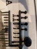
Sprue G, Part #1 (10 of them per model, or 5 Y-Wings worth) top side:

Sprue G, bottom side:

Close-up shot, top-side:

Top side is "pretty sharp" and "machined" looking on its edges, while the bottom side of the nurnie is softer, more rounded. So there are some discrepancies, as in many photos it looks like it's sharp and machine-edged on both sides.
But it doesn't look so sharp-edged on this archival Y-Wing, however, does it.

That's actually a trick of the light. In the Chronicles book, the lower left quadrant of this circle piece makes it clear that this is a sharp front and back edge, with a longer horizontal surface than front/rear surface area, which is precisely what the kit part has as its characteristics.
I take this to be the authoritative confirmed donor greeblie on Red Jammer, Gold Leader, Gold 2, and Gold 5. I am less certain on Gold 3, but this is only because I can't seem to find any conclusive pictures of this area on that particular model.
You can also get the kit re-issued later by Bandai in the 1980's, and much more common on Ebay.
I believe it was kit-bashed. I believe this for a couple of reasons:
1. Because whenever ILM could find the shape and size they were looking for in a model kit, it saved them time and money on machine-tooling.
2. Because on the actual model (unlike the DaveG perfectly-fitting 3D prints shown above), the center ring is slightly "off" of being perfectly flush with the inside of the Sealab Crane Part #59 double-sided/mirrored nurnie, as seen in the detail picture below of the Alan Ladd rear vectral
3. Because I believe I have found the part.
4. And because this part is perfectly "mismatched" to the Sealab nurnie in the same way the original was.
Here is the part on top of DaveG's 3D file printed equivalent:
Here is DaveG's 3D-file printed ring piece on top of the kit bashed part
Here are the two parts side by side.
Here is the part fitting "perfectly" inside DaveG's 3D vertical rear vectral fin, overhead view.
Here is the part fitting "perfectly" inside DaveG's 3D vertical rear vectral fin, side view.
Here are the measurements of the part, roughly 38mm inner diameter and 40mm outer diameter, but not "exactly" these numbers:
Inner diameter 38.62 (but don't take this as gospel, as I'm measuring a flexible part and each time I do it I get a different number, so even this is a "pretty close" guesstimation)
Here is the outside diameter:
Outer diameter is 40.54 (but again, don't take this number as gospel). The key is that it is pretty much 38mm on the inside and 40mm on the outside, with roughly 1/4 a milimeter (0.25mm) of wiggle room (i.e., the limitations of either my tool or my measuring abilities)
Here it is fitting inside (but just barely) into DaveG's 3D-printed horizontal rear vectral fin:
But here is where the part does not fit "perfectly" into DaveG's 3D-printed part, as the vertical ventral fin is slightly too "tight" to accept the kit bashed part, despite fitting perfectly into his other 3D-printed part: the DaveG part is a few mm shy of the full width of two Sealab Part #59's abutted to each other, which can be accommodated for inside the rear ventral ring (modified L'eggs Pantyhose container) by simply cutting off those same number of mms on the outer legs, as shown by the Gundam marketed pieces on the lower assembly in the photo below
So here it is sitting at the midpoint inside another version of the horizontal rear vectral fin, with plenty of wiggle room (but perhaps too much by 1-2mm)
So now here it is on the center part of a newly created horizontal rear vectral fin (in layout form, not yet glued together), which I believe is closer to the real original nurnie:
So where does this mystery greeblie come from?
So glad you asked...
The Entex 1/16 the Hon. C.S. Rolls 1908 Rolls Royce Silver Ghost "balloon car" released in 1975.
Sprue G, Part #1 (10 of them per model, or 5 Y-Wings worth) top side:
Sprue G, bottom side:
Close-up shot, top-side:
Top side is "pretty sharp" and "machined" looking on its edges, while the bottom side of the nurnie is softer, more rounded. So there are some discrepancies, as in many photos it looks like it's sharp and machine-edged on both sides.
But it doesn't look so sharp-edged on this archival Y-Wing, however, does it.
That's actually a trick of the light. In the Chronicles book, the lower left quadrant of this circle piece makes it clear that this is a sharp front and back edge, with a longer horizontal surface than front/rear surface area, which is precisely what the kit part has as its characteristics.
I take this to be the authoritative confirmed donor greeblie on Red Jammer, Gold Leader, Gold 2, and Gold 5. I am less certain on Gold 3, but this is only because I can't seem to find any conclusive pictures of this area on that particular model.
You can also get the kit re-issued later by Bandai in the 1980's, and much more common on Ebay.
Attachments
Last edited:
Okay, so it turns out I was wrong on my 50th birthday present -- the 1/570 Revell ship kits (HMS Prince of Wales and HMS King George V) are NOT the source of the mystery greeblie on the 4 wing subassemblies. Sorry about that -- I was fairly excited! I had found it! I was dead wrong...
It sure "looks the part" and "fits the part" but Part #64 from those two Revell ships is categorically not the part. Three reasons:
Reason One: the part does not have a top center nib that is cut off.
Reason Two: the "leg" of the real part is just a scoche longer than it is on the Revell part.
Reason Three: the actual nurnie is part #50 (unmodified) from the Nichimo 1/500 Ise (later reboxed as the Hyuga). This IS the confirmed donor. (If I had one, I'd photograph it for you and show it to you, instead all I have is a partially built model with a box top and instructions in it, which shows the part clearly)
With great claims comes greater humility... ; )
Thank you to those who illuminated my mistake and pointed me in the right direction.
Hammer3246
Sr Member
Just a thought... just a question:

Any of you ever wonder if this black "decal" (circled in red) on top of the canopy isn't actually a decal, and might be a "black" space left over after a nurnie got knocked off?

Cause here's a nurnie that kind of fits, and below it a bigger one in kind of the same shape. See the uneven-ness of the nurnie below? Now compare that shape to the black shape on the actual Red Jammer, below:

See how it is equally "uneven" on right and left side, just like the lower nurnie is?
Just wondering if it makes more sense as a "missing nurnie" or as a black paint mark or decal. And if it is a decal (from one of the train sheets, for instance), can one of you point me to which decal sheet it comes from?
Any of you ever wonder if this black "decal" (circled in red) on top of the canopy isn't actually a decal, and might be a "black" space left over after a nurnie got knocked off?
Cause here's a nurnie that kind of fits, and below it a bigger one in kind of the same shape. See the uneven-ness of the nurnie below? Now compare that shape to the black shape on the actual Red Jammer, below:
See how it is equally "uneven" on right and left side, just like the lower nurnie is?
Just wondering if it makes more sense as a "missing nurnie" or as a black paint mark or decal. And if it is a decal (from one of the train sheets, for instance), can one of you point me to which decal sheet it comes from?
Last edited:
Some nice model cars and trucks on the left side of this shot -- if they haven't been IDed yet. I'm especially curious about the three cars on the very bottom row in case you want to help out my "old man's" eyes.
Is the one on lower left a Bobby Allison Monte Carlo?
Where the sausage gets made... in a very cold basement.

What the sausage is starting to look like...

What the sausage is starting to look like...
dtssyst
Sr Member
Not only the Jammer (that looks excellent so far) but another Y in progress on the back right.
Look at all those donor kits... they are everywhere!
The Nernie heaven behind the Jammer") .
.
I love everything I see. What I don't like is the idea of a cold basement. If it were me, I would not get anything done all winter.
Look at all those donor kits... they are everywhere!
The Nernie heaven behind the Jammer
.I love everything I see. What I don't like is the idea of a cold basement. If it were me, I would not get anything done all winter.
David3
Sr Member
Just a thought... just a question:
Any of you ever wonder if this black "decal" (circled in red) on top of the canopy isn't actually a decal, and might be a "black" space left over after a nurnie got knocked off?
just noticed the greeblie/nurnie is similar to one on DaveGoldberg's escape pod
The Escape Pod Project
Similar threads
- Replies
- 5
- Views
- 1,593
- Replies
- 117
- Views
- 12,476
- Replies
- 9
- Views
- 1,522
- Replies
- 121
- Views
- 15,261