Razor Crest control lever (display stand for The Child's toy ball)

E Williams

Sr Member
RPF PREMIUM MEMBER
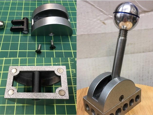
Here's a stand for Grogu's toy ball! It's an attempt to make a more or less screen accurate lever base as seen on the Razor Crest cockpit set.

IMG_8824.JPG


IMG_8823.JPG


It features recesses for magnets in the bottom for attaching to metal surfaces - doesn't your fridge need a control lever? :lol:
IMG_E8819x.jpg

Reference:

2nd episode:
razor lever2.png

Other episodes (longer lever?)
razor lever.png


I used these parts from McMaster for the ball and arm:

Aluminum Ball Knob with 1/2"-13 Threaded Hole, 1-3/8" Head Diameter
https://www.mcmaster.com/6940K47/

18-8 Stainless Steel Partially Threaded Stud 1/2"-13 Thread, 4" Long
https://www.mcmaster.com/97042A552/

The 4" stud is pictured, but I think the 5" or 6" versions are more screen accurate to the actual set.
18-8 Stainless Steel Partially Threaded Stud 1/2"-13 Thread, 5" Long -
https://www.mcmaster.com/97042A119/
18-8 Stainless Steel Partially Threaded Stud 1/2"-13 Thread, 6" Long -
https://www.mcmaster.com/97042A568/

If you already have a ball replica with different threading, here's the overall category page:
https://www.mcmaster.com/partially-threaded-studs/partially-threaded-studs-5/

Optionally, epoxy 4 neodymium disc magnets into the base, either 6x3 mm or 1/4" x 1/8"

You'll also need two 8-32 x 1/2" flat head hex drive screws for the pivot, in black oxide or stainless steel (pictured are two stainless ones, painted black as that's what the local store had, though I now see that the lever in the second episode has stainless screws):
McMaster-Carr

NOTE: When assembling, use a dab of super glue gel to lock the threads of the screws within the pivot piece. The heads of the screw will rotate against the holes in the base (apply some silicone grease under the heads). Without the glue, the screws will loosen as the lever is moved.

Files here:
 

Attachments

  • razor lever.png
    razor lever.png
    467.3 KB · Views: 199
Last edited:
I like this better than any of the other stands I have seen. My only wish would be to make the whole baseplate, the one you can see bolted down. You can still use magnets, but then also make it look bolted your fridge!
 
Thanks all!

My only wish would be to make the whole baseplate, the one you can see bolted down. You can still use magnets, but then also make it look bolted your fridge!

Yeah I should have mentioned, if you want to just display this on a (non-magnetic) shelf, you'll probably want a small steel plate or something under it to give it a wider footprint - otherwise the lever will tip over past a certain angle as it's somewhat top heavy.

Finding a steel plate sized like the baseplate in the show would be ideal, yeah. I'd just keep the magnets on the printed base as well, to simplify and avoid having to drill holes for screws to attach the base to the plate. Magnets could be attached to the back of the steel baseplate as well for that bolted on look like you mention!

Edit: The threaded stud is also useful for holding the ball knob while cutting the grooves on a lathe. I used Sprayon brand blue layout dye for the coloring (more fitting than I realized at the time as according to a recent post by lonepigeon the ANH R2-D2 prop used the Dykem version of the same stuff).
 
Last edited:
In some of the reference images it looks like there maybe some zig-zags in the top of the arch. I wonder if the real prop has a detent function.
I am thinking about altering your design to add the detents (using a ball spring from McMaster). For the baseplate I could laser-cut a panel from delrin or wood and paint it to match.
If you want to get crazy you could add a potentiometer and an aurdino and it could be made into a home smart light dimmer, or volume control.
Just something to add to the wishlist of projects I am not getting done...
 
Have at it! I'm looking forward to seeing what you come up with! :D

For the detents, since the pivot point is not concentric with the housing, you'd need to add a new semicircular feature within the shell, rather than just on the existing internal surface (as you rotate the lever away from perfectly vertical the end of the pivot gets further away from the inner surface of the base).
 
Absolutely awesome! How does the threaded ball shaft attach to the “fingers” of the base hinge? Does the completed lever sit static or can you move it back and forth?
 
What paint did you use?

Dupli-color filler primer (grey), followed by Dupli-color universal [gloss] black (Perfect Match auto lacquer BUN0100), and then 3 light coats of a silver Dupli-color. Only apply just enough of the silver to *almost* get to full coverage; the hint of black showing through will give you a more metallic look than just blasting it with wet coats. I used BGM0501 Galaxy Silver Met but pretty much any silver auto lacquer should get good results if applied this way.

Absolutely awesome! How does the threaded ball shaft attach to the “fingers” of the base hinge? Does the completed lever sit static or can you move it back and forth?

Thanks! The steel rod just friction fits into the fingers of the pivot piece - there's some flex to the fingers which allows this. I tried a pivot with an enclosed "cup" shape instead of separated "fingers" but I would have had to iterate prints to set tolerances for a friction fit without cracking the part, and it would have resulted in a model that was only good on my specific printer, so I abandoned that in favor of the fingers - there was more than enough compliance in the fingers to work even with the heavy steel stud. Yeah it will move! The screws are glued into the pivot piece, not the body/housing, so the screw-pivot-stud assembly can move within the housing. As the glue was setting I adjusted the tension to something tight enough to hold the weight of the lever but not so tight that it would damage the print or lift it off surfaces when moved.
 
Last edited:
Ah movies.. where nothing has to be the same between shots. In the shot below the shaft is very long, and the entire thing is in the wrong place. (You can even see the lever body to the left)

This is the best side-on shot that I could find:

So far I think your design is periportally very good since it seems to change as the shot requires.
 
Haha, good observation on how it moves around from scene to scene.

That second one is a great shot to pull measurements from! Based on it I think the base on mine is a little undersized at 2.5" diameter - if scaled based on a lever arm at 1/2" diameter, the base in the screencap measures out to 3" or 3.125" diameter. The 8-32 screw seems correct, though, at a head diameter of just under 3/8". The partially threaded stud should be 5.5" long (link: McMaster-Carr)

I uploaded a new base piece with the diameter increased to 3" and the width kept the same. Just for fun I drew up a baseplate as well to match :) It has nubs on one side to fit into the magnet holes of the 3" base piece and holes sized for the button head cap screws at the corners (those scale out to 8-32 as well):

1609892664096.png


Mandalorian, Ship Lever Knob.1.jpg


Mandalorian, Ship Lever Knob 2.jpg


ezgif.com-gif-maker (2).gif


Okay, so I went a bit overboard on this one. (as always) Currently I want to make this for myself and release the design files once done. (If you want me to start a separate thread let me know)

I took your general dimensions to start from, but then redid the whole model based on the side image and the ball size you selected. I ended up with a radius of 1.41" and a housing width of 1.66". The shaft is about 3/8" too long, but if you cut that off the threaded end the left over threads will be screen accurate).

I integrated the baseplate into the housing since it looks like there is a weld or casting line on the actual prop. For the corner screws I made them #8-32 tap holes, so you can drive in screws to complete the look even if you use the magnets. The corner screws are not symmetrical on the actual prop, but I couldn't bring myself to place them off center.

To get around the screw self-loosening issue I put the screw threads into the housing, with a clearance hole on the shaft holder.

I added the ball spring, with detents at both extremes and 90 degrees.

I wanted a way to be able to use this to connect to some electronics, it would make an awesome throttle for my Star Wars Squadrons VR rig. So I added a gear to drive a thin potentiometer. Then I realized that to make it feel realistic it needs some smooth friction, so I added a speed limiter on another gear. All this will make the inside look extremely technical and of course and add to the effect.

Too bad that Zenix's replica knob is threaded for M16x1.5mm and McMaster doesn't' carry anything with that thread, I may have to see what I can get on eBay, or make my own ball as you did.
 
Scale feels better at 3" diameter. I'd say skip the baseplate if you want magnets, but for just sitting on a shelf, the larger footprint of the baseplate will provide extra stability.

IMG_E8836.JPG
 
Missed the other post, wow! By all means feel free to stay in this thread rather than a new one.

To get around the screw self-loosening issue I put the screw threads into the housing, with a clearance hole on the shaft holder.

I added the ball spring, with detents at both extremes and 90 degrees.

I wanted a way to be able to use this to connect to some electronics, it would make an awesome throttle for my Star Wars Squadrons VR rig. So I added a gear to drive a thin potentiometer. Then I realized that to make it feel realistic it needs some smooth friction, so I added a speed limiter on another gear. All this will make the inside look extremely technical and of course and add to the effect.
Good idea on moving the threads to the housing - I considered it but went the other way in order to use friction as the resist. Yours should have less frustration when assembling as it won't need the glue on the threads.

Absolutely love all the additional features and functionality you added! Definitely looks extra realistic and it's so cool that you might be able to get this working in Squadrons. Wow again! Is there some sort of pre-existing USB throttle that you're transplanting to get the potentiometer incorporated?

Can't wait to give yours a print!!

The corner screws are not symmetrical on the actual prop, but I couldn't bring myself to place them off center.

Ha, I ran into the same thing when modeling the baseplate. Had to idealize a bit.

I didn't realize Zenix's wasn't 1/2-13 threaded - I came to the same conclusion he did about the shaft looking like it should be 1/2" in diameter and I had hoped his replica would work with this lever base too since I'm sure there are a lot out there.

I saw that Field Marshall just posted his own version of a replica ball (with a button!) in his ebay store - I don't know what its threading is though. Chris, care to drop in? :)
 
I am going to re-calibrate my design to fit better with zenix's version. I can live with using a thread adapter kit. (I didn't know those existed off the shelf)

It is quite difficult to get the scale perect, even with the side-on shot. The wide angle camera and perspective throw off all the non planer dimensions. Even with my CAD software set to a 35mm perspective view I find I can't quite match the perspective of the baseplate and the round portion at the same time. Oh, and the screw pivot on the actual prop isn't even perfectly centered left-right. So anything we do will have to be just artistic license and be close enough.

The image below is calibrated so that the shaft is 0.5" then the rest of the planer dimensions are put down.

Side View Dimensions.jpg
 
I have completed the design and it is ready to prototype. I ordered a ball from Custom 3D Stuff.
If you think all this stuff I did below is over kill: Well this type of design is what I do everyday.

I added an aluminum round standoff into the middle to act as a shaft.

I have created a Google Drive folder that has all the 3D STL and STEP files,. There is also an exploded diagram along with all the rest of the project files. There is also a BOM here for anyone wanting to get all the hardware. It costs $100 for the ball, thread adapter and related hardware.
I am going to prototype the 3D printed parts on a FDM machine and laser cut the flat parts. I will probably order final parts from Shapeways.

Mandalorian, Ship Lever Knob, Exploded.jpg


How about some fun image matched GIFs!

Mandalorian, Ship Lever Knob, Matched.gif


Mandalorian, Ship Lever Knob, Matched, Back.gif
 
Last edited:

Your message may be considered spam for the following reasons:

If you wish to reply despite these issues, check the box below before replying.
Be aware that malicious compliance may result in more severe penalties.
Back
Top