Rassilon
Well-Known Member
Assembly Part 1
Hi fellow RPF members and sonic lovers,") this thread is for the members that have an RCTS that would like to share there builds with other RPF members that also have an RCTS.
this thread is for the members that have an RCTS that would like to share there builds with other RPF members that also have an RCTS.
And also that would like more information and or questions on applying crackle mediums and electrics.
This information is about assembling your RCTS kit, into a working Rassilon custom sonic, for you to give them Daleks hell. :lol
By now you would have received your RCTS kit in a dry assembled form, this is so you can see that all the parts fit together and that it is all complete.
The RCTS was design to be broken down into it’s sub components, to achieve this, threads were placed at key areas to help with this feature, along with parts that were not bonded in place to help with the installation of electrical parts.
The other feature of the sonic is that some parts of the sonic can be replaced should your sonic get damaged due to extreme use or a freak unearthly accident, the sonic is by no means indestructible and the weakest part of the sonic is the acrylic shaft.
If you have any questions in regards to you RCTS build, this is the place to ask or send me a pm, or if you have suggestions to change the design, so I can make improvements on the next run, should there be one, can also do that here as well.
The Greatwazoo42 has a video of the RCTS on youtube, and is a very good example of how it go’s back together, but let us now look at doing an assemble build, and how to get the most out of your Rassilon custom sonic.
A. Braking the sonic into components
1. Remove the 3mm button head set screw by using a 2mm Allen key.
by pushing on the slider plate with one hand and at the same time placing the other hand on the crown collar remove the internal brass power slider compartment.
2. Remove the brass sleeve from inside the sonic grip.
3. Unscrew the black anodized and silver cap from the sonic grip
4. Unscrew the transmitter from the threaded ball and remove the brass tube
5. Remove the blue LED lenses cover

B. Bonding components
For any bonding of two (2) components I use a two (2) part clear resin glue.
The first part is bonding the 3.9mm brass tube into the threaded ball section.
By mixing a small amount of two-part clear resin glue and applying a small amount to the end of the brass tube and inside the hole of the threaded ball.
Inserting the brass tube all the way into the threaded ball, and making sure to remove any excess amount of glue before it dries from any parts of the thread. No less than 16mm should be protruding from the end. Ref Fig 1.2
1. Once the two-part resin glue starts to harden and not before, screw on the transmitter housing onto the threaded ball, this is so the brass tube remains straight and keeps it in true alignment, allow to dry.
And once the glue has set unscrew the transmitter housing from the threaded ball and clean out any resin glue with a 2.5mm drill. Ref Fig 1.3
2. Now you can polish the brass conduit to your specifications with a brass-polishing agent.
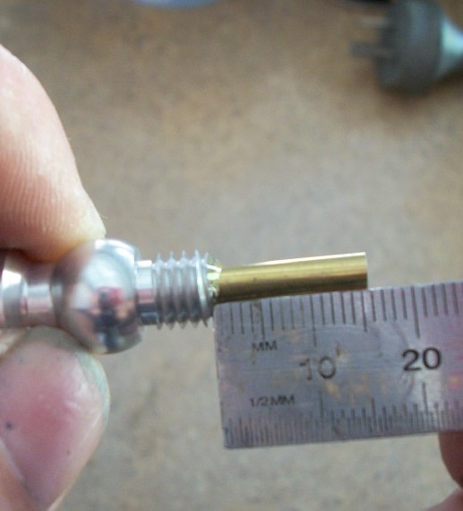
Fig 1.2

Fig 1.3
C. Crackle finishes using “Derivan” crackle medium
1. And now we come to one of the hardest parts of the Rassilon Custom Tennant Sonic and that’s the crackle finish on the grip. Aluminum is not an excellent surface to paint so you will need a specific type of paint one that is formulated for such surfaces.
And that’s the use of etch primer on Aluminum, any other type and it will not work on the Aluminum and just peal off.
The crackle effect is unique one off the kind, no two-crackle effects are the same, no matter how you do it no matter what you do no two-crackle effect is the same. So your sonic will be unique.
2. Once you have given the sonic grip a light coating of etch primer and have allowed to dry, you now can use any type of paint within reason, I used gloss black paint, as the base undercoat.


3. Next is to lay down an even coat of crackle medium, for this I used an airbrush.
This is the only way it can be applied; and get a perfect finish you must use an airbrush for this part of the application. Ref Fig 1.5 you can use foam to dab it on, but you will get very small air bubbles and that will show up on the final paint.
And it must be applied evenly to the grip and “not” allowed to gather into any particular area.
By placed the grip in the lathe and turned it by hand, at the same time as applying the crackle medium. The first layer is a coating layer and allow to sit for 8 to 10 minutes, at a temp of 25 deg C longer in cold areas. Before applying, a second coat of a much thicker layer, and allowed to sit for about 5 min, “just” leaving it longer will not allow the top coat to crack.
4. Next is to apply the top coat, this must be a water base paint as it mixes with the crackle medium and you must thin it down so it can be applied with an airbrush. Hold the airbrush about 5” to 6" from the surface of the area been painted, and apply the top coat evenly.
NOTE
Do not go over the area that you have painted, this is where you must work on a test peace first, to get your system worked out. Ref Fig 1.6
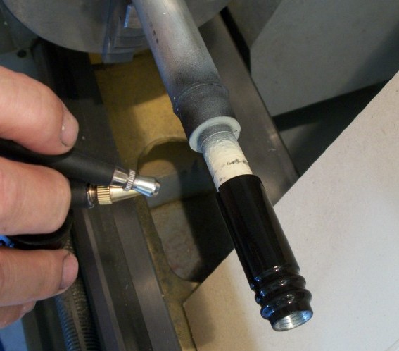
Fig 1.5
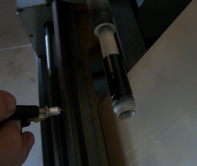
Fig 1.6
This requires fine tuning as at this point is were you get the types of crackle effect.
a. To thick and applying it to slow and you will get a cores crackle effect.
b. Applying it to thin and to fast and you will get a fine crackle effect with the base coat coming though.
c. This required practice and should be fine-tuned before any attempt is attempted on your sonic parts.
5. Once you have perfected the art of crackle finishing, give the crackle finish a sealing coat of clear acrylic paint, do not use sand paper on the surface of the crackle finish.


The above information was though experimenting with various techniques with various crackle mediums. And also very much with the help of the following members Phez and Anikin Starkiller and Robbertoe
D. Brass sleeve
Next is the brass sleeve, I used blue paint and painted just one side of the brass sleeve; you can leave this or polish this part if you so do require.
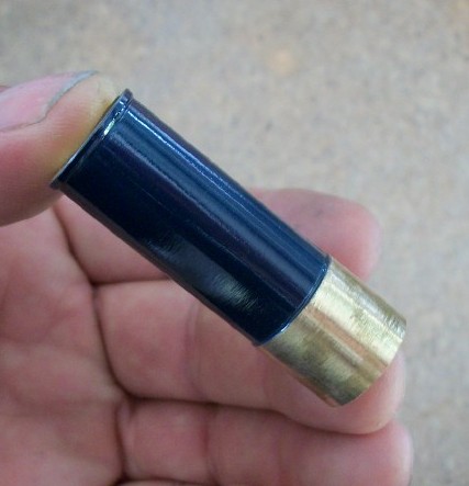
The brass sleeve has a .5mm deep recess machined into the surface, and this is the part that you would paint, as this is the part seen though the 3mm slot on the grip.
Do not allow paint to be painted onto the back section of the sleeve as this will upset the tolerances of the slider moving inside of the sleeve. So remove any paint that may get on that part of the sleeve.
Once you have panted that part and removed any paint from the back section of the sleeve, as seen in the photo above, you then can install the sleeve into the grip with the 3mm slot aligning up with the slider grove at the top of the grip.
E. Electronics
Now we come to the electrics side of the RCTS kit, and this part is fiddliest part of the build.
6. Set the pedestal drill up to drill the 2.5 mm hole for the switch extension pin.
Measure from the front of the brass slider were the acrylic rod fits into and measure back 10mm.
And make sure it is in the center of the slider, as you do not won’t to drill to one side of the slider plate as this will make the slider useless. ref fig 1.7
 Fig 1.7
7. Once you have drilled the 2.5 mm hole for the switch extension pin, the next is to drill a recess for the head of the 2.5mm x 12 long socket head cap screw to fit in to.
Using a 5mm dia drill, back drill 3mm deep Ref Fig 1.8 and Fig 1.9 the 2.5mm x 12 long socket head cap screw needs to fit just bellow the surface, remove any burs from the hole and clean. Ref Fig 1.10

Fig 1.8
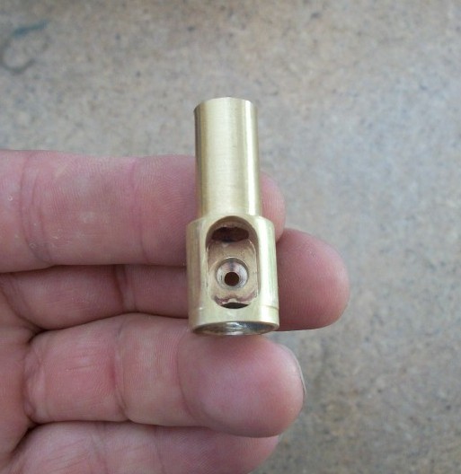
Fig 1.9

Fig 1.9
Ok that's it for this week, next week we will look into installing the tactical switch into the slider housing.
Hi fellow RPF members and sonic lovers,
this thread is for the members that have an RCTS that would like to share there builds with other RPF members that also have an RCTS.And also that would like more information and or questions on applying crackle mediums and electrics.
This information is about assembling your RCTS kit, into a working Rassilon custom sonic, for you to give them Daleks hell. :lol
By now you would have received your RCTS kit in a dry assembled form, this is so you can see that all the parts fit together and that it is all complete.
The RCTS was design to be broken down into it’s sub components, to achieve this, threads were placed at key areas to help with this feature, along with parts that were not bonded in place to help with the installation of electrical parts.
The other feature of the sonic is that some parts of the sonic can be replaced should your sonic get damaged due to extreme use or a freak unearthly accident, the sonic is by no means indestructible and the weakest part of the sonic is the acrylic shaft.
If you have any questions in regards to you RCTS build, this is the place to ask or send me a pm, or if you have suggestions to change the design, so I can make improvements on the next run, should there be one, can also do that here as well.
The Greatwazoo42 has a video of the RCTS on youtube, and is a very good example of how it go’s back together, but let us now look at doing an assemble build, and how to get the most out of your Rassilon custom sonic.
A. Braking the sonic into components
1. Remove the 3mm button head set screw by using a 2mm Allen key.
by pushing on the slider plate with one hand and at the same time placing the other hand on the crown collar remove the internal brass power slider compartment.
2. Remove the brass sleeve from inside the sonic grip.
3. Unscrew the black anodized and silver cap from the sonic grip
4. Unscrew the transmitter from the threaded ball and remove the brass tube
5. Remove the blue LED lenses cover
B. Bonding components
For any bonding of two (2) components I use a two (2) part clear resin glue.
The first part is bonding the 3.9mm brass tube into the threaded ball section.
By mixing a small amount of two-part clear resin glue and applying a small amount to the end of the brass tube and inside the hole of the threaded ball.
Inserting the brass tube all the way into the threaded ball, and making sure to remove any excess amount of glue before it dries from any parts of the thread. No less than 16mm should be protruding from the end. Ref Fig 1.2
1. Once the two-part resin glue starts to harden and not before, screw on the transmitter housing onto the threaded ball, this is so the brass tube remains straight and keeps it in true alignment, allow to dry.
And once the glue has set unscrew the transmitter housing from the threaded ball and clean out any resin glue with a 2.5mm drill. Ref Fig 1.3
2. Now you can polish the brass conduit to your specifications with a brass-polishing agent.
Fig 1.2
Fig 1.3
C. Crackle finishes using “Derivan” crackle medium
1. And now we come to one of the hardest parts of the Rassilon Custom Tennant Sonic and that’s the crackle finish on the grip. Aluminum is not an excellent surface to paint so you will need a specific type of paint one that is formulated for such surfaces.
And that’s the use of etch primer on Aluminum, any other type and it will not work on the Aluminum and just peal off.
The crackle effect is unique one off the kind, no two-crackle effects are the same, no matter how you do it no matter what you do no two-crackle effect is the same. So your sonic will be unique.
2. Once you have given the sonic grip a light coating of etch primer and have allowed to dry, you now can use any type of paint within reason, I used gloss black paint, as the base undercoat.
3. Next is to lay down an even coat of crackle medium, for this I used an airbrush.
This is the only way it can be applied; and get a perfect finish you must use an airbrush for this part of the application. Ref Fig 1.5 you can use foam to dab it on, but you will get very small air bubbles and that will show up on the final paint.
And it must be applied evenly to the grip and “not” allowed to gather into any particular area.
By placed the grip in the lathe and turned it by hand, at the same time as applying the crackle medium. The first layer is a coating layer and allow to sit for 8 to 10 minutes, at a temp of 25 deg C longer in cold areas. Before applying, a second coat of a much thicker layer, and allowed to sit for about 5 min, “just” leaving it longer will not allow the top coat to crack.
4. Next is to apply the top coat, this must be a water base paint as it mixes with the crackle medium and you must thin it down so it can be applied with an airbrush. Hold the airbrush about 5” to 6" from the surface of the area been painted, and apply the top coat evenly.
NOTE
Do not go over the area that you have painted, this is where you must work on a test peace first, to get your system worked out. Ref Fig 1.6
Fig 1.5
Fig 1.6
This requires fine tuning as at this point is were you get the types of crackle effect.
a. To thick and applying it to slow and you will get a cores crackle effect.
b. Applying it to thin and to fast and you will get a fine crackle effect with the base coat coming though.
c. This required practice and should be fine-tuned before any attempt is attempted on your sonic parts.
5. Once you have perfected the art of crackle finishing, give the crackle finish a sealing coat of clear acrylic paint, do not use sand paper on the surface of the crackle finish.
The above information was though experimenting with various techniques with various crackle mediums. And also very much with the help of the following members Phez and Anikin Starkiller and Robbertoe
D. Brass sleeve
Next is the brass sleeve, I used blue paint and painted just one side of the brass sleeve; you can leave this or polish this part if you so do require.
The brass sleeve has a .5mm deep recess machined into the surface, and this is the part that you would paint, as this is the part seen though the 3mm slot on the grip.
Do not allow paint to be painted onto the back section of the sleeve as this will upset the tolerances of the slider moving inside of the sleeve. So remove any paint that may get on that part of the sleeve.
Once you have panted that part and removed any paint from the back section of the sleeve, as seen in the photo above, you then can install the sleeve into the grip with the 3mm slot aligning up with the slider grove at the top of the grip.
E. Electronics
Now we come to the electrics side of the RCTS kit, and this part is fiddliest part of the build.
6. Set the pedestal drill up to drill the 2.5 mm hole for the switch extension pin.
Measure from the front of the brass slider were the acrylic rod fits into and measure back 10mm.
And make sure it is in the center of the slider, as you do not won’t to drill to one side of the slider plate as this will make the slider useless. ref fig 1.7
7. Once you have drilled the 2.5 mm hole for the switch extension pin, the next is to drill a recess for the head of the 2.5mm x 12 long socket head cap screw to fit in to.
Using a 5mm dia drill, back drill 3mm deep Ref Fig 1.8 and Fig 1.9 the 2.5mm x 12 long socket head cap screw needs to fit just bellow the surface, remove any burs from the hole and clean. Ref Fig 1.10
Fig 1.8
Fig 1.9
Fig 1.9
Ok that's it for this week, next week we will look into installing the tactical switch into the slider housing.
Attachments
-
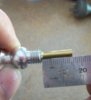 Fig 1.2.jpg67.2 KB · Views: 4,363
 -
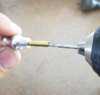 Fig 1.3.jpg69.9 KB · Views: 4,270
 -
 Fig 1.5.jpg75.2 KB · Views: 4,175
 -
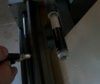 Fig 1.6.jpg77.4 KB · Views: 4,242
 -
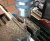 Fig 1.7.jpg141 KB · Views: 4,105
 -
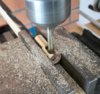 Fig 1.8.jpg141.1 KB · Views: 4,114
 -
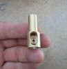 Fig 1.9.jpg67.9 KB · Views: 4,075
 -
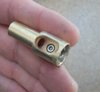 Fig 1.10.jpg66.8 KB · Views: 4,002
 -
 Fig 1.13.jpg55.7 KB · Views: 4,076
Last edited: