Please help with hoverboard parts

Grant, I am in the process of fixing a vacu-former. Once they are vacu-formed I might have to make changes.
I emailed the seller of a screen used/ prototype pitbull to see if he would email any more pictures with a ruler next to the bottom parts. He claims they are vacu-formed but they look like the resin parts. We'll see if they email pics.

Can't hurt to ask. Even if they are the vac-formed parts, it will be some ballpark numbers for great reference.

I'm not sure if you mentioned earlier in the thread, but what 3D printer are you using? The quality looks excellent from these pics.
 
Grant, I am in the process of fixing a vacu-former. Once they are vacu-formed I might have to make changes.
I emailed the seller of a screen used/ prototype pitbull to see if he would email any more pictures with a ruler next to the bottom parts. He claims they are vacu-formed but they look like the resin parts. We'll see if they email pics.

Is it the one on eBay? Because they look like standard resin to me as well. It would be great to get more measurements but I think you nailed it overall. The one measurement I would want is the exact height of the magnets and length of the bevel leading up to the top of the disk.

Okay, let me know once you fix the vaccu-form. Will be interesting to see how it looks. Do you have an ETA on when you will have it fixed?

Again, great job. :popcorn
 
Can't hurt to ask. Even if they are the vac-formed parts, it will be some ballpark numbers for great reference.

I'm not sure if you mentioned earlier in the thread, but what 3D printer are you using? The quality looks excellent from these pics.

It is the one on ebay, I agree more reference numbers are never bad for double checking.

I am using a Dimension BST1200 (click link for more info)

It is a great printer, if anyone has any questions or needs help 3d printing or drawing for 3d printing let me know.
 
I think bttf123 is selling some parts for the hoverboard!

This is mine ^^

556023_614165848598736_1688387249_n.jpg


dsc00031nx.jpg


I'm planning to change the strap though ^^
 
parts are looking great, the "hold downs" look a bit too thin to me (all over) now though, to me they looked better before when they had a bit more thickness to them

BD2D15E9-DF38-47EA-831D-9D67D4DD3EE5-22976-000009F38C906311_zps1a162313.jpg

425967_10150660489914844_764919679_n_zpsaf50f212.jpg

grvMD_zpsb4e86e44.png

lHtgS_zpse61b9b1d.png

0NUgvpU.jpg
 
Last edited:
parts are looking great, the "hold downs" look a bit too thin to me (all over) now though, to me they looked better before when they had a bit more thickness to them

You are comparing them here to the vac-uformed parts... the pre-vacuformed parts were a lot thinner.

L44MJ6G.png

9yIs15I.png


It's what you like better I guess... I like them this way because I can always choose to do the same process they did in the movie and get the same effect if desired. You can't reverse vacu-form.

I personally like them this way because they match the first parts we see when Marty steals the board.
 
I think I have accurate models of both vacu-formed and pre vacu-formed parts. Once I vacu-form them they might be the most accurate models out there!

Emma, looks like a nice board but after examining the screen used parts with a magnifying glass for months now I can spot the inaccuracies very quickly! Overall looks nice though, this thread is more for making the parts as opposed to buying them.

Now i will focus my attention on forming the parts. Anyone else notice that the rear hold down is actually going up with the flip end of the board?
 
Right—the rear bracket is angled to follow the kicktail angle upwards. GeneralFrosty, when selling his ICONS-molded parts, suggested that the rear bracket be placed in boiling water to soften it before placing it on the board and forming the angle to follow your particular board's kicktail.

So you have a few choices. You could just decide upon a certain kicktail angle, say 12 degrees, and adjust your 3D model of the rear bracket to this angle. Or you could print the angled portion of the rear-most bracket as a separate piece, so that the end-user would have to fill the crack between the angled portion of the bracket and the front part of the rear-most bracket. I for one don't like the option of printing in a material that's really flexible, though that would allow for variances in kicktail angle.
 
Last edited:
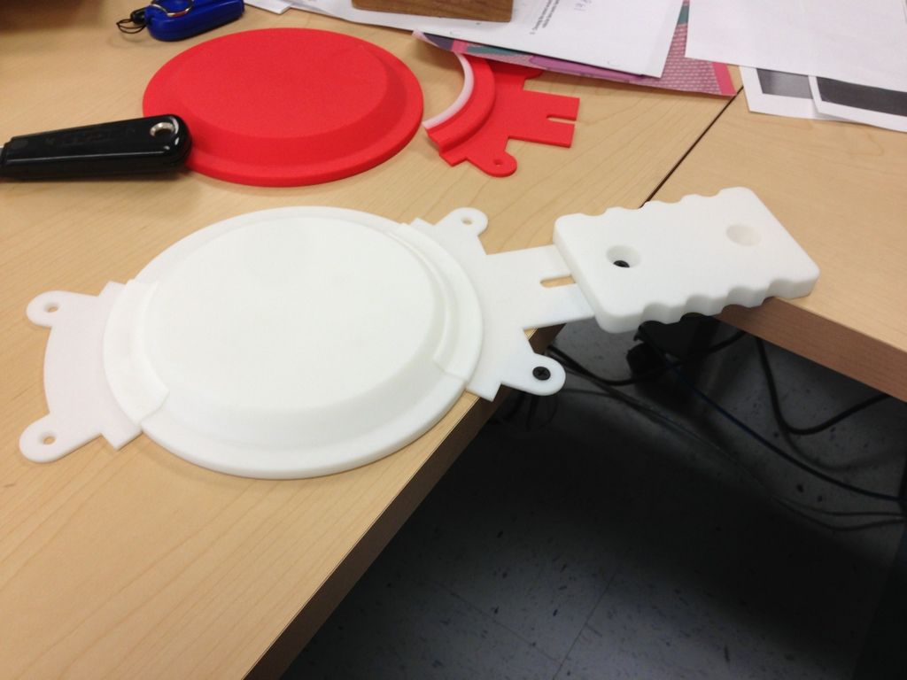
This pic should help to explain. Basically, how much of the bottom magnet parts chain sticks out over the angled kicktail comes down to:

1. How long the kicktail was on that particular board
2. How far forward/back the bottom magnet parts chain is placed on the board.

Ideally, you want the kicktail to be whatever length, and the parts chain to be shifted as far forward, as will allow only the flat portion of the rear-most bracket (which begins immediately behind the rear edge of the rear circular magnet base) to be angled upwards.

If your kicktail is longer than average, you must compensate for this by shifting your entire magnet assembly parts chain forward a bit. If your parts are positioned a bit too far back, you had better not have a long kicktail or you'll have part of the magnet base itself projecting out over the kicktail.

Notice how on Bob Gale's Almanac-burn-scene HB the kicktail start point is way too far forward in relation to the magnet parts. To prevent a gap between the magnet base and the board, the vaccu-formed magnet base is deformed downwards at the rear to follow the kicktail—not ideal, and probably not possible with resin parts unless they were heated. Even then, it just looks wonky.

kichtailanalysis.png


Now look at this Ketzer board. See how the kicktail is shorter, putting the kicktail start point JUST BEHIND the base of the magnet as it should be, and as indicated by the yellow dashed line in the pic above of Bob Gale's board? That's what you want.

holographicpattern.jpg
 
no need to alter the parts to allow for the bend of the kicktail, as mentioned above, just heat the parts up (boiling water will do) and hold/screw it in place whilst it's flexible. No need to make more work for yourself trying to cast them already curved.
 
You guys need to chill, you're overthinking it a bit. Time to call these babies done. They are perfect. Just accept that they're done and be happy. :D
 
Um, I never suggested this... I was just simply pointing it out.

It would be a bad idea because you don't know where it going to line up on the board and what angle you are going to make the kick tail. The picture Spyhunter2k showed with half the magnet is bent demonstrates that.

Again... don't do this. I didn't mean to light any fires. I was just merely addressing this because he brought it up.
 
Um, I never suggested this... I was just simply pointing it out.

It would be a bad idea because you don't know where it going to line up on the board and what angle you are going to make the kick tail.

Like I said, you'd have to inform anyone getting these parts what angle the bent rear bracket was set to so that they could ensure that their kicktail matched the bracket angle. It could also actually help to determine where your bottom should be, as far as how far forward/backward they should be placed on the bottom. You'd simply place the bracket angle directly on top of the kicktail angle and go from there.

But it was just one option I suggested to prevent having to soak resin in boiling water and bending it by hand... Didn't think most people would actually prefer dealing with the boiling water...

And overthinking...well, overthinking is what the rfp is all about. :lol
 
Last edited:
True dat.... true dat. My view is just that, they bent the brackets on the originals by hand so it's not a big deal. It's accurate to do it this way.

If you design it to conform it that would limit the option of the user to doing whichever degree of kick it was set to, and that detail varies a lot so I think it's better to have options.

My kick tail is like 10 degree's or something, it's very slight.
 
Back
Top