Not Another Daft Punk Helmet - Thomas Pepakura Build

Calmac12

New Member
Hi,

Thought I'd share some pictures of a Daft Punk Thomas helmet I'm working on. I've never done anything like this before and am sort of winging it.
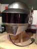
Its a pepakura base, fiberglassed with car body-filler on top. I don't plan to cast it due to a tight budget and It's not quite perfect dimension wise. The helmet is quite heavy and stinks of fibreglass. I want it to be wearable but realistically I wont be wearing it for extended periods so this isn't such an issue.

I downloaded the pep file from here: http://artbetep.deviantart.com/art/Daft-Punk-s-Electroma-Thomas-helmet-papercraft-335308771

I still have parts to smooth and touch up. The visor is 2mm PETG plastic which I cut out with a dremel and used a hair-dryer to bend to shape. I may try some car window tint film rather than dye the visor.

The ear pucks are next. I'm either going to use a 3D printer or lathe them from a hard insulation foam. What do you think?
I don't have access to the proper tools so I'm going to try my local Hacksapce for some help.

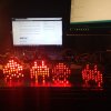
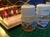
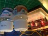
I used Sketchup to make some mock up sub-visors to hold the LEDs. I plan to paint it using Alclad Mirror Chrome then look at installing some electronics.

More info here : https://calmacprojects.wordpress.com


Ill post some more pics when I make some progress.

Cheers


IMG_5276.JPG


IMG_5285.JPG


IMG_5202.JPG


IMG_5338.JPG


IMG_5392.JPG


IMG_5405.JPG


IMG_5450.JPG


IMG_5464.JPG


IMG_5480.JPG


IMG_5481.JPG


IMG_5474.JPG
 
Last edited by a moderator:
I refuse to let this thread die. BTW, just a word of advice, Thomas's helmet has breathing holes under the visor/above the chin. Look it up.
 
Cheers Sucre!
Got the vents cut the other day. Used a dremmel and some needle files. Bit raggy but they can be touched up later.
IMG_5444.JPGIMG_5441.JPG
 
No I thought I'd start with the Thomas as it looked a bit easier.

Getting some ear pucks printed this weekend, hopefully they turn out ok!
 
Quick update, I have started work on the electronics.

The visor was laser cut from 1mm PET plastic.
IMG_5757.JPGIMG_5791.JPG


I plan to use 5 Max7219 chips to control 320 LEDs.
IMG_5662.JPG

I will use Humbrol Matt Cote with 50% thinners to diffuse the light of the red 5mm leds.
The difference can be seen in the middle led in the pic below.

IMG_5803.JPG


I used tamiya flat black to colour the back of the leds.
IMG_5807.JPG

I made a mock visor holder and will solder the LEDs together in this way to accommodate for the curve of the visor.
IMG_5790.JPGIMG_5806.JPG

More updates soon!
 

Attachments

  • IMG_5808.JPG
    IMG_5808.JPG
    858.9 KB · Views: 273
  • IMG_5808.JPG
    IMG_5808.JPG
    1.7 MB · Views: 316
Quick update, I have started work on the electronics.

The visor was laser cut from 1mm PET plastic.

I plan to use 5 Max7219 chips to control 320 LEDs.
View attachment 552353

I will use Humbrol Matt Cote with 50% thinners to diffuse the light of the red 5mm leds.
The difference can be seen in the middle led in the pic below.


I used tamiya flat black to colour the back of the leds.


I made a mock visor holder and will solder the LEDs together in this way to accommodate for the curve of the visor.


More updates soon!

Good progress. This is exactly one of the ways I am going to go in terms of electronics. It was either this or Tekparasite's method. I ordered the LED matrix from aliexpress but it's been almost a month and it still hasn't arrived. Luckily I saw the MAX7219 chips on ebay so if my matrix doesn't come, I'll do this. So go into as much detail as you can please! What are you doing for the code?
 
Good progress. This is exactly one of the ways I am going to go in terms of electronics. It was either this or Tekparasite's method. I ordered the LED matrix from aliexpress but it's been almost a month and it still hasn't arrived. Luckily I saw the MAX7219 chips on ebay so if my matrix doesn't come, I'll do this. So go into as much detail as you can please! What are you doing for the code?


Thanks Strode! Yes Tekparasite did a beautiful job. I went with this method as I couldn't find a pegboard big enough and didn't fancy drilling so many holes.

I soldered the first 8x8 matrix together last night and should have it hooked up to the MAX7219 chip by the end of the week. Fingers crossed!

Not sure about the code, I fancy having a go myself and will probably end up going to my local hacklab for help. If I get one working ill post it here.

More to come this week.

Mate, I pm'd you with something that I think might help. See if it works. Best of luck and please remember to document ;). Following with interest.
 
Progress report. I've soldered together 3 complete matrices.
These are the basic steps:


IMG_5823.JPG

Bend the short leg towards you and cut it.

IMG_5825.JPG

Make a jig and solder the cut legs together. Paint the backs with black paint.

IMG_5817.JPG

Use matt gloss to cloud the leds to aid light dispersion.

IMG_5827.JPGIMG_5828.JPG

Bend the long legs over the soldered legs. I used this black plastic piece. Cut the bent legs to about 12mm.

IMG_5831.JPG

Solder them together in the visor. This allows you to accommodate for the visor curve.

IMG_5843.JPG

I then soldered 8in wires onto each row. Figuring out the max7219 chips was a little tricky - working out which pin goes where. The chip kits come with a 10k resistor. I ordered some 27k ohm resistors to limit the current to each led. This article is useful for sizing your resistors:

http://playground.arduino.cc/Main/MAX72XXHardware

I used this code and the led panel worked:

https://www.youtube.com/watch?v=TOuKnOG8atk

Also included in the above link is a program that lets you create your own graphics. I made a space invader as a test.
Still early days in terms of coding. I only have one matrix working and will try and figure out how to cascade the graphics in the coming weeks.


IMG_5856.JPGIMG_5854.JPGIMG_5865.JPG
 
UPDATE:

Since my last post I soldered all the max chips together and tested them with the matrices. Using different colour wire for each row and column makes this easier.
I ran a few test codes and ensured the leds fit in the holder correctly.

IMG_5904.JPG

Next came the code, I searched the internet for hours and tried various codes with varying degrees of success. Someone on the arduino forum suggested this:

http://arduinocode.codeplex.com/releases/view/120493

It is by far the best way to go if you want pre made daft punk animations. Download that file and there is a daft punk example that can be configured to your setup. Highly recommend it and the Arduino forums for help. By altering the library file you can, rotate the animations to the correct orientation, swap scroll directions, create custom graphics etc.

Once I had the code sorted I began hard wiring the max chips together.
IMG_5936.JPGIMG_5928.JPGIMG_5919.JPG


I used hot glue to mount the chips to the card board top plate and heat shrink to keep the wiring as neat as possible.
Once complete it looked like this.

IMG_5931.JPG

I then started on the sidebars. I wanted them to be fairly simple so botched together a code and a rudimentary lighting system which still needs some code refinement.
I made the cases from cardboard and hot glue. The coloured panels where taken from plastic folders I found in the house. I used some cello tape to bind them all together and make them strong.

IMG_5953.JPGIMG_5918.JPGIMG_5913.JPG

I then hot glued them into place and sat back to admire the thing! The code needs to be refined, id like some buttons that let me scroll though the animations. Hopefully Ill get that sorted soon.

Video here:

https://www.youtube.com/watch?v=yWX9f7m5T7M

Cheers!

IMG_5962.JPGIMG_5977.JPG
 

Attachments

  • IMG_5876.JPG
    IMG_5876.JPG
    499 KB · Views: 365
Last edited:
It's finished! It has taken about 8/9 month in total. I hesitated on many aspects as I wanted it perfect but I heard the saying "perfection is the enemy of good enough" so I compromised on some aspects such as paint/chrome and coding. Here are some pics of the last stages of the build.

The paint turned out to be the most challenging part of the build for me. I tried Alclad gloss black base but the stuff just wouldn't dry properly.Other's seem to have similar issues. I'm not about to blame the materials though it was probably my fault. I had planned to use the mirror chrome from Alclad but it is very thin and would rub off easily unless coated with a clear coat giving a dull silver finish. I ended up having to sand the whole helmet back and re prime it. I used dial multi purpose primer then Tamiya TS14 gloss black paint. I then used Micromesh to get a deep shine. The final silver was Tamiya TS-83 metallic silver. I'm happy with the results it looks like bright silver and can be handled. I covered the helmet interior with sticky back felt.

IMG_6075.JPGIMG_6114.JPG


I tinted the visor with car window tint film. I had tried using black die but the plastic warped out of shape due to the heat.
I had intended to modify the code to incorporate buttons to cycle through the animations. This I managed to achieve but I chose to let it cycle automatically for simplicity.
I used an Arduino nano clone to control the helmet. It was hard wired to a prototype board then attached to a rudimentary mdf holder. The device is powered by a USB power pack I got cheap on ebay. I then made a simple stand from mdf.


IMG_6141.JPGIMG_6148.JPGIMG_6149.JPGIMG_6155.JPGIMG_6140.JPG

I'm really pleased with the final results. The helmet is wearable - if a little heavy. It will be used mainly as a display piece. I may try and include cooling fan later on or add more functionality to the electronics in the future. Thanks to Volpin for the inspiration and helpful build threads and my mate Mike for laser cutting my visor!

Cheers

IMG_0703.PNGIMG_6101.JPGIMG_0705.PNG
 

Attachments

  • IMG_6139.JPG
    IMG_6139.JPG
    1 MB · Views: 378
I've seen a lot it these daft punk helmet builds before but that's about the best one so far. Looks better than some of the secondary helmets that they actually wear. Good Job on the build. Now u should try ur hand at a dead mouse helmet
 
This thread is more than 6 years old.

Your message may be considered spam for the following reasons:

  1. This thread hasn't been active in some time. A new post in this thread might not contribute constructively to this discussion after so long.
If you wish to reply despite these issues, check the box below before replying.
Be aware that malicious compliance may result in more severe penalties.
Back
Top