TazMan2000
Master Member
Astounding.
TazMan2000
TazMan2000
")
New to here as I discovered this build just this week. Love the work - SO impressive! I'll be reallllllly interested to see what kind of spot light solution you come up with for the secondary hull lighting of the Starfleet insignia. Unless it has been covered in some sub page already (sorry if I missed it!).TazMan2000 - Huge thanks for the kind words!!
Duncanator – You can bring up whatever you want! I looked at doing them both ways, and ultimately I think they look pretty good this way and this mounting method saves me a ton of time. There are too many inaccuracies on the model kit to get them all fixed. I would rather have these bays mounted this way than not have shuttles! Also, huge thanks for the kinds words!!
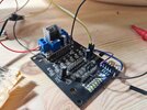
Star-Art – I am an EE, lol. I no longer do design work, but this is a great way for me to scratch that itch. I am using diodes to clamp the voltage when it goes below or above 5V or ground. Basically, the diodes provide an alternate path for the current to flow into the power supply instead of into an IC or transistor. Long term, this is not a great solution, but it can save your electronics from a hit or two, depending on how much static electricity or ESD you are discharging. So, better than nothing, but not a super stout implementation. Also, to help out on the protection side, EVERY LED has a series resistor that is installed into the model, period. This will also help protect them. The diodes though are more for the electronics that are in the base of the model.
Update #91
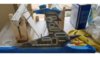
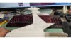
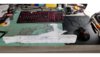
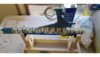
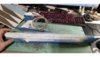
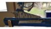
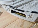
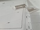
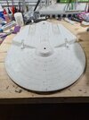
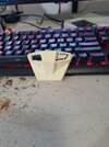
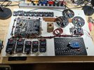
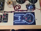
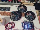
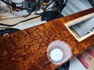
I have been working away on the 2nd Reliant nacelle. I have completed 4 of the 7 areas that need to be painted, about 75% of it. I have the front and rear portion of the nacelle left to do. Doing 6 layers of paint for the aztecing takes some serious time, but having so many layers of paneling looks amazing, the pictures don’t do the model justice. Should be done in the next few days. All of the pics are of the WIP for the nacelle painting.
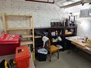
No progress on the O Club, arboretum, Enterprise nacelles or the bases. I did get the latest Cameo in though, which will cut through styrene much better than the old model. The newer model can put down something like 20 pounds of force on the cutting blade, which is 6ish times more than the old model, which will get it through 20 thousand styrene, which I need cut for many parts. Woohoo!
On a side note, I really enjoy doing the aztecing. Not sure why, but I find it very relaxing!
Cheers
James
Hi James - sorry for delayed response from my side. Thank you for taking the time to answer my question. I'll poke around and try to find the detailed, original post. Good luck with everything and please, stay healthy!TazMan2000 - Huge thanks for the kind words!!
Duncanator – You can bring up whatever you want! I looked at doing them both ways, and ultimately I think they look pretty good this way and this mounting method saves me a ton of time. There are too many inaccuracies on the model kit to get them all fixed. I would rather have these bays mounted this way than not have shuttles! Also, huge thanks for the kinds words!!
Star-Art – I am an EE, lol. I no longer do design work, but this is a great way for me to scratch that itch. I am using diodes to clamp the voltage when it goes below or above 5V or ground. Basically, the diodes provide an alternate path for the current to flow into the power supply instead of into an IC or transistor. Long term, this is not a great solution, but it can save your electronics from a hit or two, depending on how much static electricity or ESD you are discharging. So, better than nothing, but not a super stout implementation. Also, to help out on the protection side, EVERY LED has a series resistor that is installed into the model, period. This will also help protect them. The diodes though are more for the electronics that are in the base of the model.
Update #91
I have been working away on the 2nd Reliant nacelle. I have completed 4 of the 7 areas that need to be painted, about 75% of it. I have the front and rear portion of the nacelle left to do. Doing 6 layers of paint for the aztecing takes some serious time, but having so many layers of paneling looks amazing, the pictures don’t do the model justice. Should be done in the next few days. All of the pics are of the WIP for the nacelle painting.
No progress on the O Club, arboretum, Enterprise nacelles or the bases. I did get the latest Cameo in though, which will cut through styrene much better than the old model. The newer model can put down something like 20 pounds of force on the cutting blade, which is 6ish times more than the old model, which will get it through 20 thousand styrene, which I need cut for many parts. Woohoo!
On a side note, I really enjoy doing the aztecing. Not sure why, but I find it very relaxing!
Cheers
James
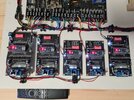

 , this will be about 500 total, which will take some time. That made me really grumpy. I was having this really weird issue and it took me a while to trouble shoot it, but I did. Hopefully will have the new transistor before Christmas, so I can swap em all out over the holiday, since we can’t travel anywhere here in Germany.
You're definitely not the only one!