Mutara Nebula DeBoers E and R Build

Update #79


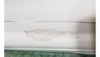
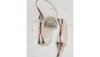
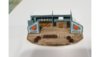
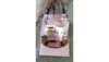
Good and bad update. The good news, every 3 years I build a new PC, and push all my hardware down. Basically, wife gets upgraded and kids get upgraded. Reload the OS, redo all of the heat sink compound, clean everything out, dust, etc. Got 3 of the PCs done, down to 1 PC and the server. A few more days, lots of data on the server to move around. The new machine is super fast, and everyone is happy with their upgrades. I had to vacuum up 974.7 dust bunnies though. So, the model build, I have started to Apoxi sculpt reinforce the Reliant hull and to build up the areas needed to install the shuttle bay. That is the first pic. A lot of writing on failure. First off, you would think with such HUGE models, there would be plenty of room inside the model to do what you need to do. NOT even close. So, the first pic is of a light box enabled way to get light down into the shuttle bays, it of course works perfectly, however, if I want to glue the top of the model onto the bottom of the model, this will not work so good. Pic 3 and pic 4 are shots of the shuttle bay inside with that light box on top. Looks great, but does not fit. So, my solution was to flatten 8 LEDs and glue them onto the top of the shuttle bay light piece. I do not have any pics, but the shuttle bay looks as good as pic 3 and 4. Next pic is of the shuttles glued into the bay. I still have to put the ladder back in, but will wait to do that. I keep knocking it off with my big thumbs. Pic 7 is of the really cool light boxes on the shuttle bay, and pic 8 is of what they look like. I was conflicted on how I like the look but decided that it was cool, even if you could see some of the fiber and LEDs in light boxes. HOWEVER, this will not fit into the model, because the model is not big enough, LOL. So, I am going to close off all of the openings I worked very hard to get put into the model with some sort of door or something, not sure and only light the shuttle bay from the top down. Something like 5 hours of work flushed, but oh well, life goes on. On another note, much more work on the base completed. Matt at LaserFire Creations is an awesome dude helping me out on this build. The base size is settled on, and I am looking for some cool wood veneer to add to the base.


Cheers,

James


Slide1.JPG
Slide2.JPG
Slide3.JPG
Slide4.JPG
Slide5.JPG
Slide6.JPG
Slide7.JPG
Slide8.JPG
 
Sorry you are having so many issues with your build of the Reliant. The pics look great and I like your idea of showing off the shuttle bays. One of the scales is off, either the bay itself or the model. I hope you can salvage something out of this. Good luck.
 
I made the shuttle bay as big as I could, and it seems to come out at 1/350, while the model is 1/270. All of the models in the bay are also 1/350. I looked to find 1/270 and couldn't and the effort for the minor difference in size wasn't worth the squeeze in my OCB opinion.

Update #80


Lots of good progress over the last week. More base coat white was sprayed down, cleaning up more nit noid trouble areas. They are starting to go away for good, which is cool. I am working on the read of the Reliant, I need to get the base white down before I install and match up the shuttle bays. I will do some more painting tomorrow, to many errands today. I shoot paint every hour or so, and do other work when it is drying. One of the shuttle bays is pretty much done. The pics do not do the shuttle bay justice. In person it looks fantastic, in the photos just ok. A crap load of wires hanging off of the back now though. I did learn a few things, I made a few uncorrectable mistakes. I placed the runway LEDs right next to each other without any light blocking, this will not be a problem on the other shuttle bay, but it will cause some weird effects on this one. Basically, if all of the LEDs were in order, there would be a fade or following effect. As one pair of fiver optics lit up, the ones next to it would be dim, which I think will actually be really cool. However, it will not work this way. When I do video of it I will point out the error. I also had to do a lot of after the fact light blocking with my aluminum tape. So, I will get the extra light blocking installed pre LED installation. I will also line the LEDs and lights in the bay in order to get that cool precede and recede effect of lighting. So two pics of the shuttle bay lit up. The approach lights will sequence, and the green and red LEDs next to the shuttle roll up doors will blink. The travel pod will also have blinking red, green and white flashers on it. Hopefully you will be able to see the effects on the travel pod. One slide shows all of the wires, which is a crazy amount. I need to tune the LED intensity for the shuttle bay, too bright looks really wrong, so the over head lights, the lights behind the blue windows and all of the fiber optic LEDs will be tunable to get the desired result. One photo to show the small scale of the bay, that is a quarter. Also today we went to the Michaels sale, and I picked up an R2D2 rolling bin. This thing is awesome, and really cleaned up my work area and is allowing me to store stuff waaaay easier. I plan on getting another one tomorrow. Super excited by a rolling thingy, lol. So, will work on the other shuttle bay this week, and try and finish up the base paint on a bunch of parts. I keep finding little issues to fix. At some point I will need to stop that, but not quite there yet. When I get the Reliant nacelles to 105% goodness, plan on painting the aztecing


Cheers,

James


Slide1.JPG
Slide2.JPG
Slide3.JPG
Slide4.JPG
Slide5.JPG
 
Update #??

I am not writing this from my normal machine, I am TDY and away from the house but wanted to post some cool pics. I got the second shuttle bay complete for the Reliant this last weekend, and took some shots of the two shuttle bays in the Reliant, looking good. The second shuttle bay went much better than the first, took the lessons learned and made this one a lot better. Next step is to finish the white paint on the back of the Reliant and work on getting the shuttle bays installed level and then finish the gap between the shuttle bay and Reliant hull. These two shuttle bays add a crap load of wires to the model, LOL. For the base onto revision 5 of the design. I plan on using 6 inchPVC pipe for the rotating portions on the base, but 6 inch PVC pipe is really 6.25 inches! So got the files updated and off to LaserFire. I have some big personal news, but waiting on confirmation before I post. This could delay the build for over a half year, more to come on that.


Cheers,

James


Slide1.JPG
Slide2.JPG
Slide3.JPG
Slide4.JPG
Slide5.JPG
 
Update #82


Back to my house after driving around the south for the last week. Got to visit some cool places. Still waiting on confirmation of my news, which was a short notice tasker to deploy to some place not in CONUS for some amount of time. So prepping all of the stuff I am going to take with me. The plan will be to do the panels for the bases for the models while over there. I will also write the code for the various boards, shield board, landing bay lights boards and the shuttle blinking lights board. If I have time will start working on the main control board code. I will also see if I can figure out how to get some custom PCBs made for hopefully not a lot of money. Since all of the LEDs run at between 8-12V I need to put a transistor in between the Arduinos and the LEDs so I do not blow up the Arduinos with the too high voltage. So making the voltage translation boards instead of hand wiring everything will save a ton of time and slightly increase reliability. So, not all of the work was prep work today, I did my first aztecing on the Reliant nacelle, and I am actually really happy with how it came out! This is not usually how I feel about my work, so refreshing. Lol Painting the aztecing took 6 layers of paint, so the amount of work to get the whole model painted is going to be stupid, but oh well. I think the end effect will be worth it. I do want to tweak the colors to help get some more separation on the final product. Also, the last photo of the toned down multi layer aztecing does not do the paint job justice, it looks waaaaaay better in person. I am sending off the no kidding final file for the base tonight which is also really exciting.


Cheers,

James


Slide1.JPG
Slide2.JPG
Slide3.JPG
Slide4.JPG
 
Slide1.JPG
Slide2.JPG
Slide3.JPG
Slide4.JPG
Slide5.JPG
Slide6.JPG
Slide7.JPG
Update #83


So basically been painting all week, and closing in on finishing the first Reliant nacelle, woohoo. In general the paint adherence is AMAZING compared to acrylic. I am loving these lacquer paints from AK Interactive. However, the random not sticking paint reared its ugly head again, a couple shots of the damage, but since there are so many layers and little squares, it is actually quite easy to patch up the affected areas and make them blend in. So in a way, the 6-8 layers of paint for the aztecing on the Reliant makes patch work easy. Sand, tape off a little square around the blemish, paint with one of the aztecing colors and then tone down with some base white paint. Problem solved. I touched up the black on the outer part of the nacelle to show the daughter, it looks great, with two minor exceptions which will get fixed. I also got my duck egg blue equivalent mixed up, so ready for that color when done with the aztecing. After that, put down the copper and touch up the inner nacelle grill and this assembly is almost done. Progress.


Cheers,

James
 
Update #83


Paint Guide What I am using to paint the models


Lacquer Paints

Base White Poly Transpar Ultra Hide White McKenzie.com


I use AK Interactive Lacquer Paints WHICH ARE AWESOME!

Reliant Specific

Aztec Colors

Medium Gray 1 Bottle Flat White 004 + 20 drops of NATO Black 082

Medium Dark Gray 1 Bottle Flat White 004 + 40 drops of NATO Black 082

Light Blue 1 Bottle Flat White 004 + 4 drops of Blue 011

Light Brown 1 Bottle Flat White 004 + 20 drops of Ochre 016 and 4 drops of NATO Black 082


Duck Egg Blue 1 Bottle Flat White 004 + 3 drops of Blue 011


Shuttle Bay

Light Grey 054

Deck Tan 019

Yellow 007

Signal Red 005


Shuttles Poly Transpar Ultra Hide White


Yellow highlights/RCS Thrusters/Blinky Lights Yellow 007

Red Highlights and lines Signal Red 005


Here is my paint selection so far. I am using AK Interactive Lacquers and they are AMAZING!


All I have been doing the last week is painting, getting close. I need to do some touch ups on one side, I bet you can tell which ones from the pics. This nacelle is about done, will get wrapped up in a super soft cloth to protect that paint job and then I will probably pause on the model, still not sure when/if deploying, but if going will take a break from the model, and get ready to walk out the door with all of the electronics I need. I have also mailed off the part examples for the base, and the materials have been ordered to make the bases. So there is some progress there. I am still looking for the veneer I like to veneer the bases, probably do it in black and white ebony, but still undecided atm. When I decide, will post some pics of the veneer that is going on the bases. Progress continues, I should get the shuttle bays in the Reliant to fit, I do not know, maybe. Oh and I suck at taking pics, the paint job is pretty darn awesome in person, one of the pics gives you an idea of all of the layers in there and the layering, 8-9 layers in certain areas.


Cheers,

James


Slide1.JPG
Slide2.JPG
Slide3.JPG
Slide4.JPG
 
Thanks!!

Update #84


Well, I am putting the models into mothballs. Going into storage on my gaming table and will be covered with some sheets, need to keep the dust off! Last pic is of a lot of my electronic stuff I am taking with me, not pictured soldering iron and a few other items. Since I have the box layout done, I can actually start writing the code and doing layouts of the box bottom, how all of the boards are going to fit. Matt over at LaserFire will ship me the front and rear plates to me over in my deployed location and the rest of the box stuff to the house. So here is what I plan on getting done over the 7ish months I am gone.

1. Write the code for all of the boards, how many boards, not sure. I know there is 1 mega Arduino per box, and then some number of nano Arduinos. I have to get all of the Starling Tech boards integrated, they handle a lot of the effects and sound effects. I have tried and failed to get twinkle effects he has done, so going with his code. Also, Stan is an awesome dude!

2. Get the box bottom layout complete

3. Design and get manufactured all of the LED voltage interface boards. Since the LEDs will ruin from 5V-12V, depending on what they are doing in the model, I have to have a way for the Arduino to control that LED without getting destroyed by the voltage driving that LED, when I have the boards done, will post a little circuit for you. I also have to have a way to integrate all of the manual switches into the Arduino control.

4. Wire up all of the switches that are going into the panels. Something like 200 switches, will give an exact number later. However, some of those switches have a TON of wires needing to be soldered to them. The little rotary switches have something like 16 wires on them, and they are small.


I am sure I am forgetting something, but that is the plan. So when I get back, more painting, gluing etc. I will have the box components and will go up to Dallas to do the veneer work. I need to figure out what wood species I want to use for the veneering. So not much is going to be posted over the next few months, I am sad, but when Uncle Sam says go, you go.


Cheers,

James


Slide1.JPG
Slide2.JPG
Slide3.JPG
Slide4.JPG
 
Thanks, so far all is going well! Also have found some time to do some soldering and PCB layout!

Update #85


Well, I am getting some model work done over here. Not the painting or glue or building of the model type, but work none the less. Which is kind of cool. A big chunk was soldering wires to a boat load of switches, something like 140 so far, with more to come. See pic 1. The other REALLY cool thing I have figured out how to do cheaply over here is printed circuit board design, or PCB. I am an EE with a decade of design experience, from a few years ago, but PCB design, layout and prototyping was expensive. Not anymore. I found a website called EasyEDA, which has a decent schematic capture program and a pretty good layout tool. I have designed 2 boards so far, but only have purchased 1 of them, my voltage adjuster board, which is needed to have Arduino 5V output driving a 12V LED power. The cool thing though is that the boards are laid out to help in wiring of the base. The first board is dumb, there is no software involved, but I was able to add LEDs on board, some simple ESD protection for the silicone on the board and the Arduino driving it. The intent is to be able to have all of the software and hardware in the base tested and working WITHOUT having the model installed. And when I install the model, all of the wires will use a 0.1 inch connector. The idea would be to ship the model and base NOT attached. We shall see. The graphic that is attached below, hopefully isn’t too big, is of the second board. This board does have an Arduino on it and drives the 13 LEDs for the landing lights in the three different shuttle bays. The board also allows for the lights to go forwards or backwards and with 5 different speeds. There are controls on the base to allow for this. The funny thing between all of the hardware costs, this is like a $50 feature for each shuttle bay. The rotary switches are expensive. The next board I am working on is the main control board for the Arduino MEGA. The nice thing about this is that I will be able to mount all of the little daughter boards to this guy and minimize wiring. The last pic is of my landing bay hardware and software mock up.


Cheers,

James


Slide1.jpg
Slide2.JPG
Slide3.JPG
 
Update #86


Since I can’t work on the model, I continue to work on the base. I have been putting in a ton of effort on getting all of the controls worked out and what they do. I have a 6 page design document, lol, on how it all works. The bad thing is this has taken some serious time, but the good thing, I have the time to do that over here. That design document helps me go in and design all of the printed circuit boards PCBs that will be in the base. Another interesting item is that a schematic is just a portion of how to design a PCB, how the parts lay down on there is also really important. So to help me out on that side, I have been mocking up the base in Power Point, everything is sized pretty close to what the PCB and where I want them. Doing all this helps me lay out the connectors on the board appropriately and will greatly help in wire management. Those 90ish switches all have at least 2 wires, some upwards of 16, so wire management is a very important concern. I don’t want a rats nest of crap going crazy in the base. You get an idea of the scale of the PCBs and the number, I have a few more to design. I am going to incorporate more into the main control board. I am going to have to go to 4 layers on the main board, so the cost does up too much adding a few more square inches to have more functionality on there. All the boards in this pic are at least 1 revision out, will post an updated base pic at some point. Probably when I do my final check on all of the routing etc.


Also attached some pics of my first test run from the PCB maker, these are really good looking boards.


Cheers,

James


Base Bottom Positioning Work.jpg
PCB Top.jpg
 
Update #87


Still working on getting all of the PCBs designed and laid out. 4 of the 5 boards are done, going to wait a few days, then go through them one more time with a fine tooth comb. The 4 smaller boards are an Interface Board, RCS Thruster/Shuttle Bay landing lights boards, Attitude Controller Board and a Power Distribution Board. I am still doing some work on the large control board. I have all of the power control circuitry in there, but I am still working on the interrupt stuff, and some other external logic I think I will need. Also going to add some generic foot prints for ICs so I can add additional stuff if I have forgotten something. Even though the cost is not great for these, I don’t want to do more than 1 revision on them. Soldering all the darn parts on will take a day. The picture shown is for the Reliant, the Enterprise is a subset of this, 2 fewer boards is all. I am missing the audio control card, no biggie. I also have the Bill of Materials, BOMs, done for the 4 smaller cards and will order parts when I order the boards. The cost difference in ordering straight from China is amazing, although shipping eats up some of that, still cheaper ordering from there.


Cheers,

James

Reliant PCB Layout.jpg
 
I must admit i skim read your last few posts as im abotu to go eat, but at quick glance it looks like youre using a bunch of blue pills or arduinos...

Are you driving all your leds direct off the micros?

You really dont need to... It would be much simpler to setup a TLC5947 chain and control it all off 1 micro? Cheaper to do too... You might also only need 1 or 2 TLC5947s, as theyre 24 channels each.
 
MangyDog, lol

I am using a bunch of Arduinos, and they are pretty cheap. A lot of the lighting effects have timing requirements behind them, so instead of writing some really complicated code, and bashing my head against a wall, I am breaking all of that code up into smaller much easier chunks, just spread out across purpose built hardware. The micros are NOT driving the vast majority of LEDs on the model. One reason for the shear amount of components. There is an npn transistor on almost all of the LED driver lines. This will allow me to tune the brightness of the various sections of the ships, cause each of those boards up there also has 1 or more voltage regulator driving the LED power controlled by the transistors. So if you look at how I am putting in light boxes everywhere in the ship, this is why. I can now control each individual section on or off, and what voltage being supplied to that section. Another benefit is I can do some crude PWM if needed since I have so many processors in here. So, simplified the code by adding more hardware, but not that much, since all the LEDs needed a voltage translator transistor in there. A to the number of LEDs that are controlled, and not individual LEDs, but sections, on the Reliant the number in something like 200, just in the shuttle bay, there are 50 or so. Each of those LEDs do something. I can't wait for some video of them doing stuff! I am trying to create as much kinetic activity as possible in the models, hope that makes sense!

Update #88

Thanks gentlemen for the kind words as always. A quick update, all 7 PCBs are done and are being made and all of the components are purchased. I expect to get the boards and pats into Texas in 10 days or so, then 2 weeks to ship over here, then start assembling them and then write all of the code that will be needed to get them all to work properly. In the meantime, have to do a revision on all of the base acrylic so LaserFire can get the bases done. Matt won't be doing the finish work, I will be doing that myself. I love doing veneer work and found some amazing quilted Kosipo veneer, which is AMAZING. I look forward to getting the veneer down and putting a gloss polished finish on it. The veneer will be on the sides of the bases. I get all of my veneer at veneersupplies.com and I have always been very satisfied with what they have provided. So, while not apparent, the amount of work to get the boards designed and in production has been stupid. Almost all of my free time for the last 6 weeks was devoted to this effort. One very small benefit of not being home.

Cheers,
James

Kosipo.jpg
 
This is a truly amazing thread. Just reading about your paint adhesion issues have stressed me beyond measure... your resiliency is incredible. I must admit that I probably would’ve scooped everything up an fit of frustration and tossed the lot in the trash a long time ago. Those bays are just NEAT!!

I’m very much looking forward to future updates!

Cheers! — James
 
I must admit after reading your reply I'm more inclined to say you really should be using tlc5947 chains...

It's actually really not that complicated to program... You start with a scheduler library, and from there you can run multiple led sequences all with there own fps. As all your doing is updating there channels. So all other led channels will not have there data changed on each chain update...

So say you have one led that flashes once a second, and another led that flashes once every 3... You set one task schedule to run once 1000ms the other 3000......

Also tlc5947 is 12bit pwm controlled.

Only downside is you need 3 or 4 gpios to run the chip. You could use ws2811 ic, those are 3 channels per chip, (as usually they run rgb leds) that only needs 1 io to send data....
 
Update #89

I have been spending almost all of my off time hours soldering! Which I guess is a good thing, LOL. I have about half of one of the main control boards left to solder, but the soldering is about done. I will start working on all of the wiring needed to get the boards to all talk and power each other, then off to writing the code. One of the board’s code is written, but still have a bunch to go. Hopefully, the stupid amount of LEDs shows why it is easier to slap another Arduino down rather than write more complicated code, even with using GPIOs and 5947s. A lot of the LEDs are timer driven, and I need to use my interrupts for external inputs. I am also much faster at the hardware side and even with custom hardware, the boards are a few bucks each. Another really COOL thing is that I came up with a solution for my problem on my TOS Bridge build. I couldn’t come up with a way to pack in a ton of little LEDs and have a way to connect each fiber optic line to them, I can now with the layout and board design tools from EasyEDA. When I get home, will take a look at designing those boards and getting them made. This won’t derail the E and R build though. Need to power through and get these two girls done.

So the first pic is of the 1st completed set of boards on a mockup of the base for the models. The base is 2’ x 3’ to give you a sense of scale and perspective. Over the next few days will be doing all of the power wiring and other wiring needed to get everything talking to everything else.

Next pic is of the second set of boards, I still need to finish up the control board. Need a break though!

Next pic is of the main control board. Three of the daughter boards are from Starling Tech. He does great work and can’t recommend him enough for your electronic needs. There are a ton of wires left that are needed to get all of these boards to work together.

Next pic is of the shield control board. This board is for the shields up display that is in each of the bases. A single board does both the Reliant and Enterprise.

Next pic is of the stack up for the congested part of the hardware. Really hard to see, but there is a Mega Arduino tucked underneath the control board that runs the whole shebang.

Last pic is of the attitude control board. Each of these boards needs a little swing arm to detect the limits of the rotation. I design a part that you cut out of the PCB to make it work. There is also another part in the PCB used to connect the acrylic dial face to the motor assembly on the control board. I am really happy this came out as well as it did, was super worried it would all stack up correctly.

Another reason to do the base like this is that I can write and design all of the control stuff in the base and make sure everything works without having the models here. The way it is all designed is that I can also transport the model off of the base, then easily connect the model to the base when I arrive at wherever the model’s home ends up being.

Progress!

Cheers,
James

20190712_175216.jpg
20190712_175223.jpg
20190712_175236.jpg
20190712_175252.jpg
20190712_175314.jpg
20190712_175430.jpg
 
Update #90


A bit o time has past since my last update. I returned from ym deployment, yeah, spent the holidays with the family not working on the models, yeah/boo, but now I have the time to pick them up again. Happy to be working on them again! As to the base electronics, all of the boards are pretty much built and I have done some debugging on them. However, I want the actual physical bases to be here to finish up the electronics and install everything into the bases. I am having difficulty getting them built. No details here, I am hopeful I won’t have to switch vendors. He has made the last 3 bases for my models and really want to get the 4th out of him. My problem is that we are moving this summer, so I need them here so I can do all of the finish work while I have access to my veneer workshop up in Dallas. Fingers crossed.


The good thing about 8 months of away from the models is that all of the paint adhesion issues have come forward and the areas that I was having issues with have been identified. I don’t think more paint was going to bubble up waiting longer. So, I stripped everything down, applied the paint adhesion stuff, again, and I am down to a few very stubborn areas that won’t adhere properly. So, the solution I came up with while sitting down, where I do all of my best critical thinking is to remove a millimeter of material or so from each of the affected areas, go back in with Apoxie sculpt for a new base material and paint over that. The pics show the bubble, which is really hard to see on camera, the flaking of the paint and then the dremmeling of that area. So the Apoxi is going in tonight, and will sand and paint this weekend. Hopefully this will all be sorted this weekend and I can put this to bed, finally!!


I am also doing the paint and lighting work for the officer club for the Enterprise. I painted the O club that I got off of Shapeways, the base colors are in. I have added the LED lighting and stuck it in the E. I will need to fabricate some sort of ceiling for the club though, was not counting on that, you can see LEDs and the underneath of the model, and we can’t have that. Otherwise, I am super happy with the way it has come out.


I have started working on the arboretum, but instead of scratch building it , like I did for the shuttle bays, I have a buddy who owns a 3d printer farm, he does work for people around town, and he is going to CAD up the arboretum and print it on a Prussa resin printer. The print quality that this equipment produces is astonishing, and this will save me a TON of time. Hopefully should have the rough parts in a week or two. Not having the bases is frustrating, I need the base to finish the E’s mounting system, so then I can set the wiring and arboretum final location. Stuck on that, but at least, forward progress on the forest.


The second Reliant nacelle is about ready to be painted. I am doing the final sanding and polishing on the base paint job this weekend, might even start to shoot colors on it, another large assembly coming to an end.


I have also done a ton of work on adding the reinforcement to the large glue ups. Basically adding in Apoxi Sculpt around the perimeter of the E and R, need a larger surface area to glue up, you can’t just glue up the edges of the fiberglass.


Glad to be back and working on the actual models!


Cheers,

James
 

Attachments

  • Slide5.JPG
    Slide5.JPG
    58.3 KB · Views: 197
  • Slide6.JPG
    Slide6.JPG
    59.5 KB · Views: 199
  • Slide7.JPG
    Slide7.JPG
    80.3 KB · Views: 196
  • Slide1.JPG
    Slide1.JPG
    65.2 KB · Views: 220
  • Slide2.JPG
    Slide2.JPG
    90.6 KB · Views: 217
  • Slide3.JPG
    Slide3.JPG
    79.7 KB · Views: 234
  • Slide4.JPG
    Slide4.JPG
    102.6 KB · Views: 212

Your message may be considered spam for the following reasons:

If you wish to reply despite these issues, check the box below before replying.
Be aware that malicious compliance may result in more severe penalties.
Back
Top