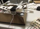
MPC X-Wing - Internally Motorized S-Foils

Robin Hood Disney GIF
purely unintentional chip pun, but I'll take credit for it :lol:
 
Hagoth,
Still watching and learning. Creating the mechanical movement desired in your model certainly requires some trial and error. Part of the design process. A credit to your demonstrated ability to persist and find solutions. My father in law was an airframe engineer on the F-14. He helped with maintenance issues on its innovative, at the time, swept wing mechanism.
Sometimes you need to get creative to adapt things to something that already exists. That's part of the fun of a project like this and it generates plenty of ideas for even better designs in the future. I'm sure you have picked up on similar thoughts with our 5' Falcon project.

F-14 is a wonderful plane and piece of engineering. Very capable. I have an unfinished Monogram 1:48 scale version of it that I started as a teenager.
 
Printing new wings with proper dimensions to test out the function of the different configurations. These are for the PM-1A. This time the attachment tab has a .21mm tapper to it. I hope this proves out the modification required to the actual kit wings to make the tips touch in the closed position and eliminate that annoying wing gap.

IMG_6074.JPG

The new wings for the PM-2A will be printed next. PM-2A modification all designed up and ready to go. Since the top covers are interchangeable I'll only have to print the frame portion for this version to get started.

TL PM-2A New Wing.jpg

Having only one model kit, printing these test wings greatly speeds up the parallel iteration and development process of the two configurations of mechanisms. It is also a trial design run for a much larger 1:24 scale fully printed X-Wing to come.

More updates on the way.
 
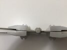
Had a chance to work on some test assemblies today. The prototype wing modifications worked out as planned. Both configurations for attaching the wings now result in the wing tips closing completely. Kit wing modifications for attachment to both mechanism designs have been validated with replicas of the kit wings.

The kit wings are not flat and the wing roots are not 90 degrees from the rest of the wing. This results in annoying wing gaps at the tips when the wings are in the closed position.
IMG_6098.JPG

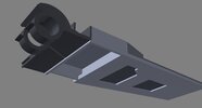
When adapting the wings of the kit to the PM-1A (no folding wing root panels and exposed bearings) the end of the trimmed wing root needs to be sanded down to 1mm thick or less. Laying the wings on a flat surface with 3 pieces of paper under the wing root edge (left side of the rendering) and a 1mm high sanding guard on the front and back then sanding off anything above it should give the desired tapper. No sanding should take place at the end close to the engine box.
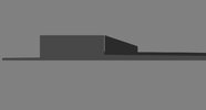
Wing Mod.jpg

For the PM-2A with folding wing root panels the corner between the small root stub and the vertical wall of the engine box needs to be sanded to 90 degrees. This need to be done on the printed mechanism part adn on the kit wing. No sanding at the top of either mating part will give the proper taper as it mates flush to the vertical wing mount face on the mechanism. This configuration is much easier to adapt the wings to for getting them flat in the closed position but is a little more complicated to assemble with the wing root panels that will go in after wign attachment.
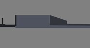
Wind Mod 2.jpg

Not sure if all kits wings are warped more or less than mine so be aware that the possibility of some adjustments might be in order to get things to line up as intended. I'm considering printing out a wing base and cutting up the kit wings to use the surface details and glue them to the printed base just to get a flatter wing but keep the kit details.

At any rate here are the progress pictures of the adaption in practice.

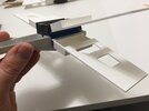
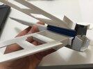
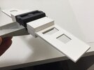
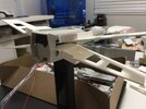
Wings getting attached to the various mechanism wing roots.
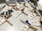
IMG_6088.JPG

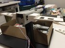
Assembled Units. PM-1A in the back and PM-2A in the front. The new test top wing covers fit nicely on both.
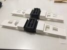
IMG_6090.JPGIMG_6097.JPG

PM-1A test fit in the model body with wings open and closed. Nice solid operation with no body wiggle and a satisfying synchronized motion.
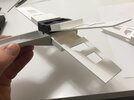
IMG_6092.JPGIMG_6093.JPG

PM-2A test fit in the model body with wings open and closed. Same solid operation with no body wiggle and a satisfying synchronized motion.
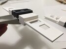
IMG_6095.JPGIMG_6096.JPGIMG_6094.JPG

Very pleased with the wing gap correction measures for both of these.

For anyone that just wants a manual wing mechanism upgrade for their kit both of these configurations are ready for release.
I'll post details soon.

Next step tonight or Monday will be soldering leads onto motors. We shall see how it goes.
Then I can finally test a motorized version working with the body around it!

Thanks for stopping by to check out the progress.
 
Really nice tests! Eager to see a vid of those folding wings (y)
Yeah, so am I. Work is in the way of my special interest. Or should I say my special interest is distracting me from work? :p

Glued the wires down with a dot of super glue to the remains of the wire leads pad last night since solder makes a very poor structural element. Seems to have worked really well. Can hardly wait till 5:30 tonight.
 

Attachments

  • 185374AF-9EC4-4FC1-9601-EC476E4EFC7E.jpeg
    185374AF-9EC4-4FC1-9601-EC476E4EFC7E.jpeg
    25.3 KB · Views: 86
Success!

Took a lot longer to get everything put together than I planned. Super glue didn't stick well to the wire strip on motors. Need to figure out something else. Maybe a two part epoxy. Wired everything up and then realized I needed to take if all apart again to put it in the motor mount and the model hull. Powered it up and discovered that when the unit is in the body I need to drive the motors at 6V instead of 4.5 when they are nominally rated for 5. Still using my manual stepper driver so things move slow but in the end it worked. With the parts just dry fit together there is some backlash evident that will be eliminated when the parts are glued but the concept has been proven to work. I did get a video of the wings opening and closing but will need to edit it for posting to Youtube and then I can link to it here.
At any rate here are some pictures.

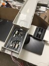
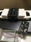
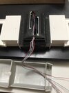
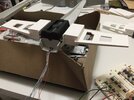
Wired up and placed in the lower hull.
IMG_6112.JPGIMG_6106.JPGIMG_6105.JPG

Still shots of closed and opened. First powered test.
IMG_6101.JPGIMG_6102.JPG

Second powered test with the fuselage top half in place. This is what I shot the video of. The backlash shows up when the wings close again.
(Edit - turns out the video was without the top fuselage on the model)
IMG_6104.JPGIMG_6103.JPG

Full video will be coming soon. I will probably speed up the frames since it took 5 min of button pushing to open and then close the wings with a manual stepper driver.

Thanks for sticking around to see the progress!
 
Last edited:
Here is the video of the wing action. Enjoy!


Direct link to video

As mentioned in the video manually positioned units are available for purchase now. Just email me (contact info at the end of the video) or PM me here to place an order.

PM-1A (exposed spindle bearings) is $36 plus shipping.
PM-2A (folding wings root panels) is $41 plus shipping.

As a special offer to those on this thread I will make the mechanism STL files available for the same prices as above if you want to print your own. Limited to personal use only please. Keep in mind that the mechanism is a small model kit in and of itself and finish work will be required for assembly and fit.

I'm confident enough in the effectiveness of motorization method that I can make purchase of the motor driver pack components as it currently stands open to discussion. Depends on how much of your own work one is willing to do at this point.

These announcements do not end this project. They just mark a milestone in the progress of it.
The end of this project will eventually be a completed Red 11 X-wing with an internal power source and driver boards. Still a long ways to go.

Thanks for following along!
 
Last edited:
Not much to show.
Redoing the Arduino motor driver method I had in mind after trying to run an A4988 stepper driver on 5 VDC and smoked a power supply. :rolleyes:

Basically the new method will automate my manual driver with transistors instead of switches. We shall see if I can make this work.

Not dead yet.
 
This is really outstanding work Hagoth, from concept to execution. I have no doubt you will have this wired and operating smoothly in no time!

Cheers,
Josh
 
Success!

Took a lot longer to get everything put together than I planned. Super glue didn't stick well to the wire strip on motors. Need to figure out something else. Maybe a two part epoxy. Wired everything up and then realized I needed to take if all apart again to put it in the motor mount and the model hull. Powered it up and discovered that when the unit is in the body I need to drive the motors at 6V instead of 4.5 when they are nominally rated for 5. Still using my manual stepper driver so things move slow but in the end it worked. With the parts just dry fit together there is some backlash evident that will be eliminated when the parts are glued but the concept has been proven to work. I did get a video of the wings opening and closing but will need to edit it for posting to Youtube and then I can link to it here.
At any rate here are some pictures.

Wired up and placed in the lower hull.
View attachment 1463821View attachment 1463820View attachment 1463819

Still shots of closed and opened. First powered test.
View attachment 1463815View attachment 1463816

Second powered test with the fuselage top half in place. This is what I shot the video of. The backlash shows up when the wings close again.
(Edit - turns out the video was without the top fuselage on the model)
View attachment 1463818View attachment 1463817

Full video will be coming soon. I will probably speed up the frames since it took 5 min of button pushing to open and then close the wings with a manual stepper driver.

Thanks for sticking around to see the progress!
Great motor & actuator photographs Hagoth. Especially sharing the dual rack and pinion design. I have to stop watching this thread. Gives me too many ideas. Again, thanks for providing the past motor resource location.
 
Last edited:
Been reviewing a ton of electronics stuff and how too's. This forum is as good a source for research as anywhere else so I'll ask here. Anyone following this thread that is an Arduino/transistor electronics expert that could help figure out what I need to consider here? I'm pretty sure I need a resistor between the Arduino pin-outs to the transistor base but not sure how to figure out the ohm's required or if it might be safe to drive two transistor base's off one pin-out and if I can do so then should they be in parallel or series? I'll post a schematic of the motor dive setup if it helps with getting help.
 
Last edited:

Your message may be considered spam for the following reasons:

If you wish to reply despite these issues, check the box below before replying.
Be aware that malicious compliance may result in more severe penalties.
Back
Top