Hagoth
Sr Member
Thank you for the interest! I spent hours looking for possible options that could fit in the space under the unit. After purchasing a few potential solutions I figured out really quick that a high gear reduction system was necessary. Most of the motor options that are small enough to fit are made for moving super light camera shutters or focus lenses so they have almost no force output or torque. AliExpress turned out to be the best source for me with the most variety of options on a single site.Clever mechanical design concept Hagoth. Will follow this thread with great interest. Please advise source of your motors / actuators. I have not seen these types of motorized screw versions.
I have been using inexpensive, geared box type 6v dc micro motors purchased off of Amazon. The manufacturer uses metal gearing. Many rpm selections. I have been using 32 pitch gears to avoid slipping teeth on the motor pinion driving a RC car spur gear. Gets me adequate torque on the rotating screw shaft. That arrangement eliminates motor head room for tight locations. The “traveling nut“ technique provides movement length not available by remote control servos and bell cranks.
Again, kindly provide your manufacturer & source of your actuators. Your electronic source would be a bonus and perhaps avoid limit switches on my project. Thanks In advance.
I settled on stepper motors for the very reason you mentioned. I could avoid the need for limit switches for the stops and vary the travel distance and speed with Arduino code. It did take a bit of figuring to learn how to drive them manually for testing.
Here is the source link for the motors I ended up using:
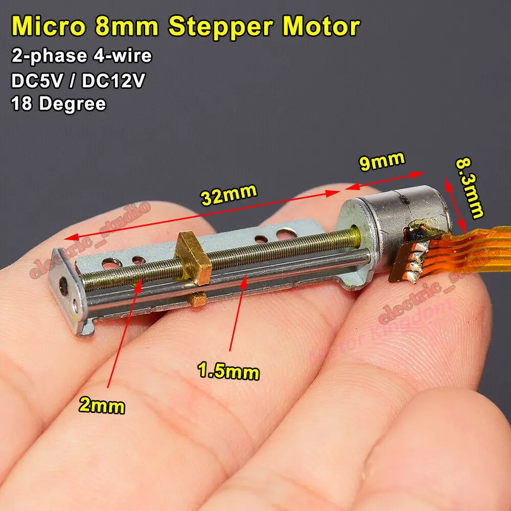
3.75US $ 5% OFF|Micro 8mm Precision Screw Stepper Motor 2-phase 4-wire Stroke 30mm Linear Stepping Motor Diy Xyz Printer - Dc Motor - AliExpress
Smarter Shopping, Better Living! Aliexpress.com
Here is the other one I considered but the mounting bracket turned out to be cumbersome and just got in the way. Might be useful for another project.
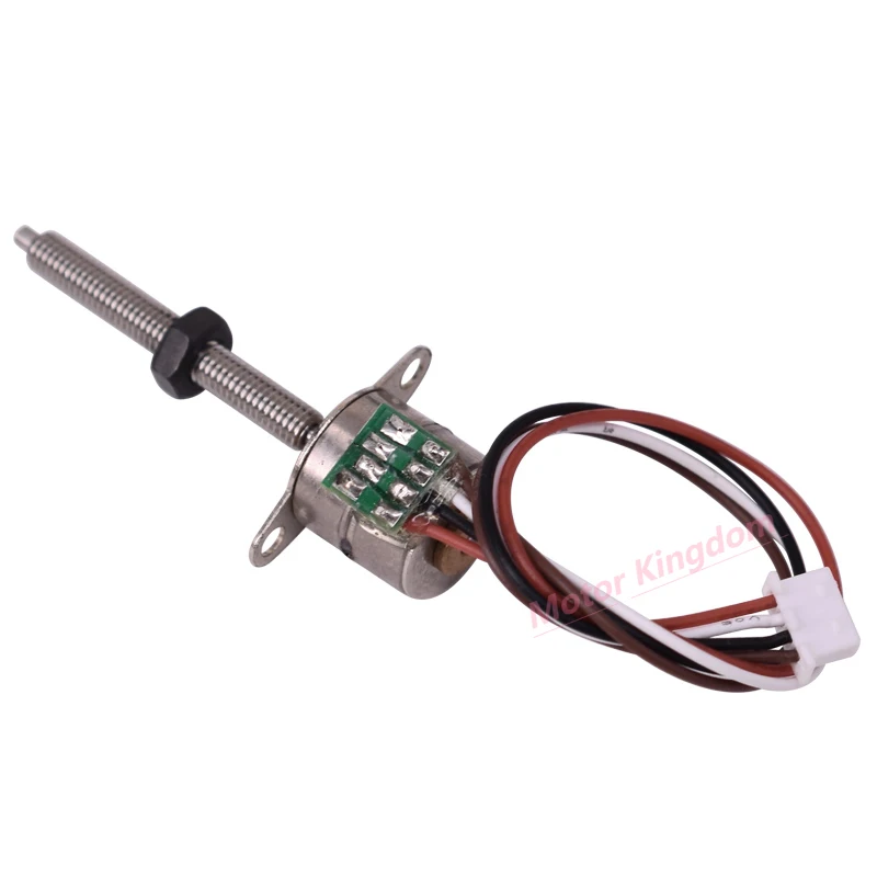
6.89US $ 5% OFF|23mm Long Linear Actuator Micro 10mm Stepping Motor 5v 2 Phase 4 Wire Mini Precision Step Motor - Stepper Motor - AliExpress
Smarter Shopping, Better Living! Aliexpress.com
The others are somewhere on the site but I'm not finding the links at the moment.
 I'm probably going to replace the PM-B1 prototype with the new configuration if I ever get around to finishing my Pro-Shop build, because motorizing it is just too cool not to do.


