MPC X-Wing - Internally Motorized S-Foils

Hagoth

Sr Member
This thread is the next phase of my long running project to internally motorize the wing action of an MPC X-Wing kit. You are welcome to follow along and see where this ends up. First off, here is what I'm starting from.

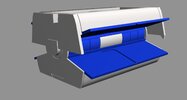
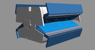
The basic wing action mechanism design has already been completed. The design synchronizes the wings opening and eliminates the wobble in the body. I have two wing attachment configurations.

The first is the PM-1A. The kit wings are intended to be trimmed and attach between the wing root mounts so they cover up the channels for the wires to the engine lights.
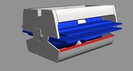
PM-1A Closed.jpgPM-1A Open.jpg

The second is the PM-2A. This one has folding wing root panels that cover up the channels for the wires to the engine lights and the rotation bearings. The kit wings are intended to be trimmed short to attach to the vertical flat surface with only a small alignment lip butting against the wing root panels edge.
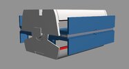
PM-2A Closed.jpgPM-2A Open.jpg

A common drive mechanism link is on the bottom of both of these. The goal is to have a common motorized drive attachment for either mechanism configuration that fits underneath it inside the model kit. I have a volume 8.5mm high, 30mm wide, and 52mm long to work with.
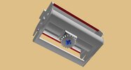
Drive Key.jpg

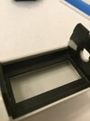
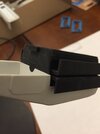
To prepare the kit body to have a drive mechanism installed I needed to remove the wing pivot posts from the upper half and cut holes for future wire runs
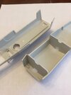
IMG_5933.JPG

Printed examples of each type of unit coming up next.
 
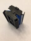
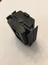
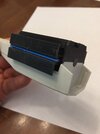
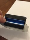
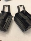
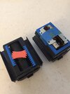
Here are the printed mechanisms. These units are almost complete model kits by themselves. Especially the PM-2A with the folding wing root panels.

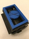
Latest version of the PM-1A parts after removing all the support structure, some surface clean up, and full assembly.
IMG_5934.JPGIMG_5935.JPGIMG_5936.JPG

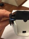
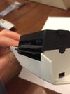
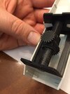
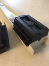
And fit and function test in the kit hull pieces. Super smooth manual function of the wing mounts.
IMG_5937.JPGIMG_5938.JPGIMG_5939.JPG

Now for the new stuff. PM-2A printed assembly coming next.
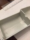
 
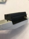
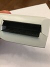
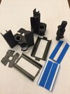
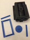
Here are the PM-2A parts after removing the support structure, some surface clean up and full assembly. There are a lot of parts to this mechanism. 19 primary parts.
IMG_5943.JPGIMG_5948.JPGIMG_5944.JPGIMG_5945.JPG
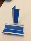
I show the folding wing root panels already assembled. They are made up of 2 main panels and 2 mounting bars hinged together with rubber cement soaked paper strips. This is the same technique used on the Pro-Shop 1:35 scale version of these mechanism wing root panels which have held up under repeated opening and closing for about a year now. It worked well enough to take the concept and miniaturize it for the MPC kit. The panels need to be no more than 0.5mm thick for them to fit in the wing gap. Since I have not installed the engine wires yet through the mechanism the panels are just a dry fit at this point.

Fit and function test in the kit hull. Holding in the wing root panels to show the intent. Again super smooth manual function of the wing mounts.
IMG_5946.JPGIMG_5947.JPG

On the PM-2A I added a second vertical strip just inboard of the frame. The effect when assembled is the second panel hides the gear features of the wing mounts. You can see how the gear features still are visible in the PM-1A after assembly. While mostly hidden once the wings are attached I think I like the look and will modify the PM-1A design to have the same feature. Also makes for a stronger wing assembly part.

IMG_5952.JPGIMG_5949.JPGIMG_5951.JPG

Possible motors next. Already know this will have to be a rack and pinion style drive.
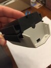
 
Last edited:
Insert another insight first. Actually another possible body modification is going to be needed especially for the PM-2A configuration. Since the wing roots of the PM-2A are thicker than the PM-1A (where half the thickness is the model kit wings) plus have the folding panels in between the wing mounts hit the body before the wings are fully open to the minimum spread angle. Depending on what reference photo is used and as best as I can determine the wings seem to have a spread of 33 - 36 degrees. I like the wider look so I will need to trim down some of the body side wall for the unit to fully open to 36 degrees.
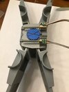
I can use the mechanism frame as a guide to trim down to. You can see in the images that about 1mm will need to be trimmed off.
IMG_5953.JPGIMG_5954.JPG
 
Final post for tonight... maybe. It's nice to have a day that I can make a lot of progress and catch up on thoughts ratteling around in my head. Also things are starting to click together really fast so I don't want to stop testing things out.

Here is the rack and pinion test configuration I came up with. It will get modified from here to match up to the selected motors. The lines show the arc of movement from fully closed to fully open. I need a linear motor that can travel about 8 mm.
IMG_5959.JPGIMG_5958.JPGIMG_5960.JPG

Here are the motor options I considered. As you can see they are quite small. The mechanism requires almost no force to move but I will need to overcome the weight of the wings to get thing going. Going to need some serious gear reduction ratio to pull off the required starting torque. Also going to use two of them in series for more torque and to make the unit more stable.
IMG_5955.JPG

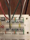
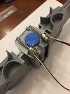
I needed something to test out the 5V motors with so here is a manual driver I wired up to test if they will even work or not.

First set of buttons on the left provide positive direction to the first coil (A+ A-). The third set supplies positive power to the second coil (B+ B-). The second set supplies power to the first coil in the oposite direction (A- A+). The far right set supplies power to the second coil in the opposite direction (B- B+). Each button push move the motors one step or 18 degrees of rotation. I press the buttons in series (1,3,2,4) to move one direction and reverse the order (4,2,3,1) to move the other direction. I have the leads wired in series so once I determine what is the A coil and what is the B coil on a particular motor I can pair them up manually make the motors move.
IMG_5956.JPG
 
Last edited:
IT WORKS! IT WORKS! IT WORKS!!!
At least on a proof of concept level...
I have a motor combination that can drive the mechanism and potentially still fit underneath the unit! :D :cool:

A progress post on refinements will be made this coming week!

In the mean time a Happy Easter to all those who celebrate it!
 
Man, this is so awesome! I still have your prototype from years ago for the Pro Shop X-wing kit... Sorry I haven't finished that build, heh. But this version is lightyears better since it can easily fit internal motors on it! :D
 
Clever mechanical design concept Hagoth. Will follow this thread with great interest. Please advise source of your motors / actuators. I have not seen these types of motorized screw versions.

I have been using inexpensive, geared box type 6v dc micro motors purchased off of Amazon. The manufacturer uses metal gearing. Many rpm selections. I have been using 32 pitch gears to avoid slipping teeth on the motor pinion driving a RC car spur gear. Gets me adequate torque on the rotating screw shaft. That arrangement eliminates motor head room for tight locations. The “traveling nut“ technique provides movement length not available by remote control servos and bell cranks.

Again, kindly provide your manufacturer & source of your actuators. Your electronic source would be a bonus and perhaps avoid limit switches on my project. Thanks In advance.
 
Thank you everyone for the shared excitement. I'll answer the questions above shortly in the posts following this but first, a huge amount of progress since the last update to share.

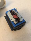
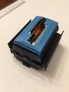
The biggest news is I have the motor bracket designed and working and can fit the entire unit in the body. I'm loving how compact this is. The unit feels so solid and works so smoothly. Here are the pictures going backwards from assembled to exploded

Here is how the motor pack fits on the bottom of the mechanism. Very snug and very compact. The use of stepper motors eliminates the need for limit switches and will allow me to control the distance of travel down the road when linked to an Arduino controlled driver tied to a blue tooth command input. Yeah, I know this is only the beginning of a very ambitious final project goal. But, this is a huge leap of progress for the long time dream.
IMG_5963.JPG.

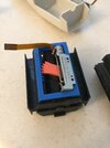
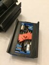
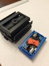
Popping it off the bottom of the mechanism you can see how the three frames all fit together holding everything in place and keeping the movement of the parts aligned. Lots of different colors here as parts were printed on multiple printers at the same time to speed up testing the revisions as I made enhancement changes.
IMG_5965.JPG

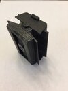
The hour glass shape of the pinion evolved trying out the different motors as parts kept getting in the way of each other when going through the full range of motion. The solution I hinted at on Saturday was the result of retrying a dismissed motor that did not work with the round pinion when the motors it was modified for ended up not fitting in the body because of the mounting arms. Solution unfolding before my eyes. The racks were then modified to fully engage and capture the motors drive plate.
IMG_5964.JPG

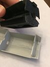
The majority of work was refining the motor mount to hold the motors securely and still interface with the other parts. A nice feature is that it does not have a front or back orientation. Like the rest of the unit everything but the bulkhead panels are reversible.
IMG_5966.JPG

The motors snap in solid now and are removable after test fitting. A very important feature of the development process.
IMG_5967.JPG

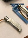
Motor details. I sourced them off of Ali Express. Links and info on them to come shortly.
IMG_5968.JPG

This part gave me grief when it came to fitting everything in the body. There is slight rise in the surface profile just before the front bulkhead. It is covered up by the frame and once accounted for in the space measurements I realized had negative zero clearance. This required 2 more iterations of the motor bracket to determine the profile and still I had to file the surfaces to get them to clear. Now the front of the unit contacts the bottom of the wing bay. Worth the effort because in the end it worked! It does mean that some custom fit and finish will be required.
IMG_5969.JPG

And finally the fully assembled unit with drive motor assembly attached fitting perfectly in the body.
IMG_5970.JPGIMG_5971.JPG

Space wise and design wise this works. I can only test the unit under power outside of the body at this point since the leads to the motors don't extend out the front or back of the unit far enough to connect to the manual driver I built. This fact now dictates the next stage of development. I need to solder on longer wire leads (teeny tiny contacts) and connect the motors in series inside the motor bracket. Also, an additional design modification to the motor mount frame needs to be made since I have no clearance between it and the model. Channels need to be added for the motor and engine light wires to pass through the drive unit to the front or back of the model. A battery pack will likely go between the rear bulkhead and the butt plate and the control circut boards will be up front under the R2 unit and in front of the cockpit. R2's head is intended to be the on/off switch. This coming weekend I hope to complete the wire channel design and longer motor lead soldering part of the project.

Thanks for following!
 
Man, this is so awesome! I still have your prototype from years ago for the Pro Shop X-wing kit... Sorry I haven't finished that build, heh. But this version is lightyears better since it can easily fit internal motors on it! :D
Hi Millennium! I've wondered what the state of that prototype was! Thanks again for the use of your kit to create it. It has evolved into a PM-2B configuration with the folding wing root panels. You can see it here:
Direct link to video
The PM-1B like you have is still available as well.

As for motorizing the Pro-Shop mechanism I have a concept rattling around in my head that will use a worm gear on a stepper to drive a toothed disk that attaches to the front drive shaft. Since the action is about 200 degrees of rotation if is way too far for a linear drive. But, since there are already two levels of gear reduction built into the unit I can use a more direct drive method and still have it work. Should be a very flat drive unit that fits on the front right under R2. Here is the concept mock-up I've been playing with. One of the motors will be operated in reverse if I use two and put them in series. This will be a future project.

IMG_5972.JPGIMG_5973.JPG

Cheers my friend!
 
Last edited:

Your message may be considered spam for the following reasons:

If you wish to reply despite these issues, check the box below before replying.
Be aware that malicious compliance may result in more severe penalties.
Back
Top