Making Room for My 1/350 TOS Enterprise!

I’ve been jumping back and forth from the Shuttle Bay lighting and the Bussard assemblies.

First, the Bay lights.

My altered bay lighting is almost there.

I’ve been able to solder wires right up on the base of the LED without killing them.

100_0186_zps9a2f68c3.jpg


It’s a good thing these LEDs were a little shorter than the originals. I’m going to enlarge the very top of the hole enough to get that LED base lip to drop in, getting that much flatter. A little dab of liquid electrical tape for insulation and I’m good to go.

100_0185_zps291dce13.jpg


It’s these two side LEDs on the ‘Q’ line leading to the Shuttle Bay I was looking to replace, but I’ve reconsidered and decided not to remove them and use them to better light the aft end around the bay.

100_0184_zps7c0d9688.jpg


Rather than cutting and splicing the original lighting kit, I made this ‘Y’ adapter so I can plug in both the original ‘Q’ line and my new ‘Q2’ line.

100_0183_zpsacb9f724.jpg


I do think I will go back and make the adapter shorter.

In fact, I will be adding these small connectors throughout the lighting kit (more on that later).

I’ll be back with my Bussard endeavors. It will take me a little time to type up.

Stay tuned.
 
Last edited:
Ok, Bussard Collecting…

Something I really want for this build is later accessibility to the electronics wherever possible.

With that in mind I made some light mods to the Bussard Collector assemblies. I want to loosen the tight fitting parts.

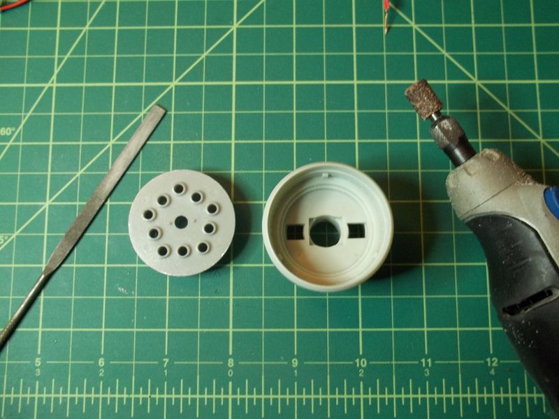
The Light and Motor housing: I used my Dremel to slightly open the hole the motor goes through. It is still a snug fit, but easier to push it through.

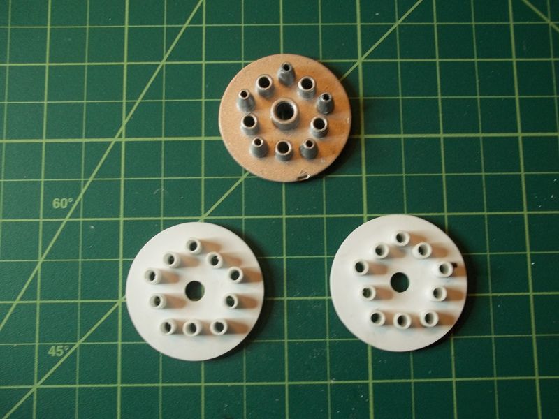
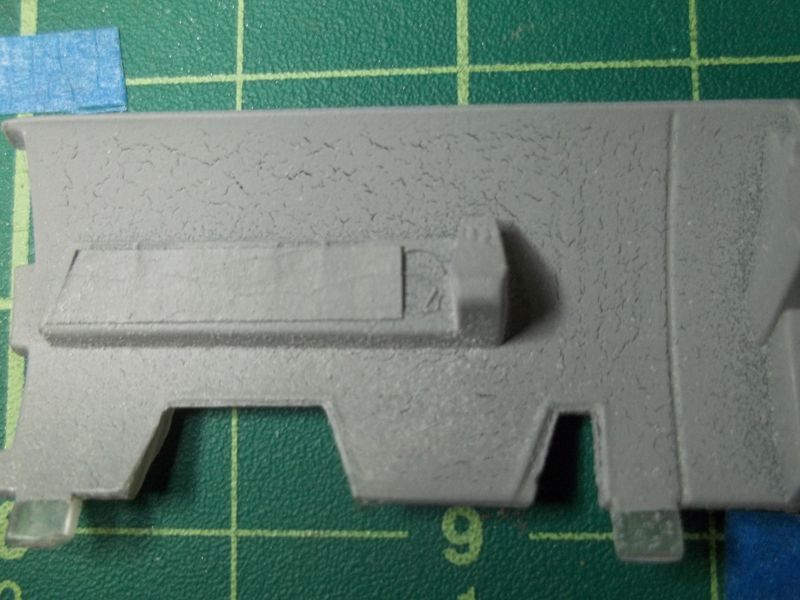
The Lighting Back Plate: I lightly filed the outer edge of the back plate so it would also pop in and out much easier.

100_0203_zps9b56ae3c.jpg


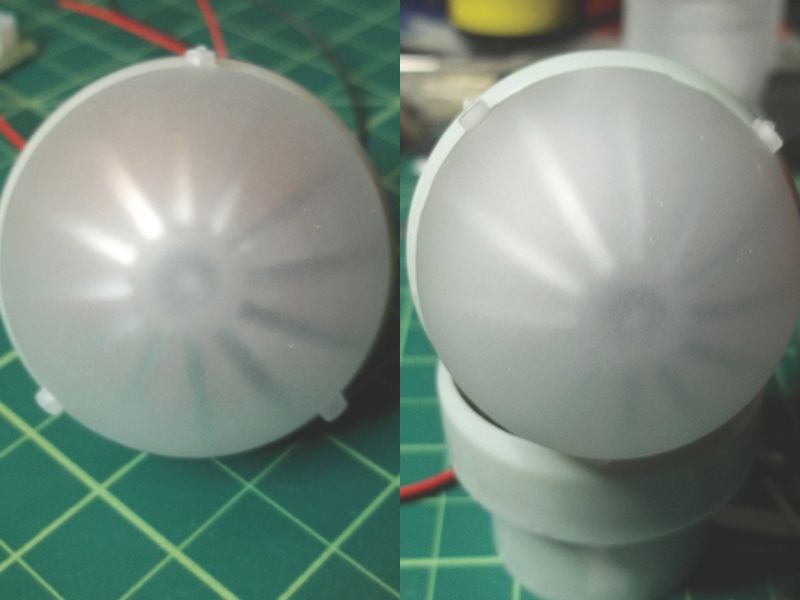
The Inner Bussard Dome: I took a 2mm drill bit and turned it by hand and raked it like a file in the inner dome shaft to help it remove from the motor easier.

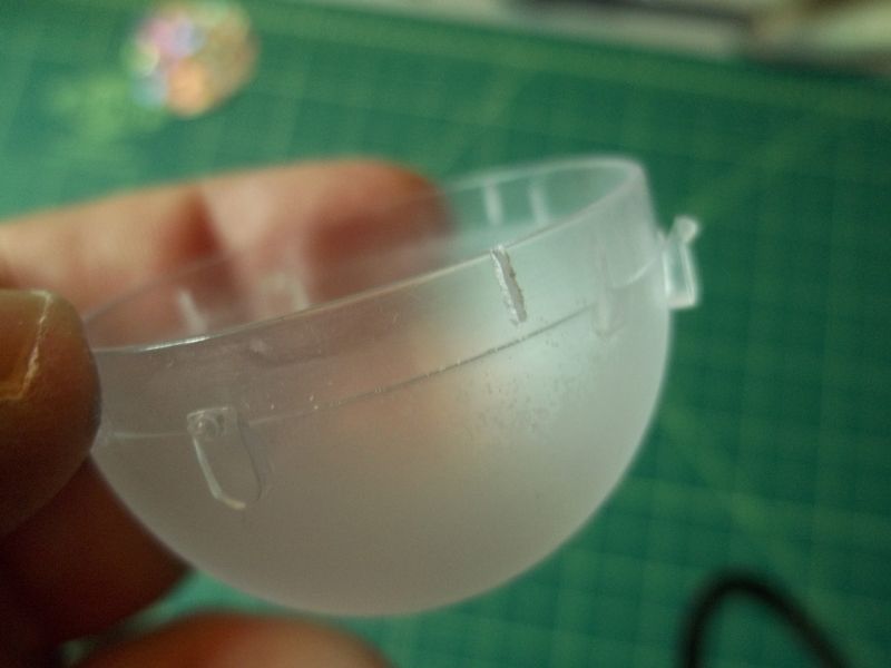
The Outer Bussard Dome: I used a razor saw and cut the rim in three places so it would remove easier.

100_0188_zpsaec8227f.jpg


Now everything still goes snugly together, yet can come back apart without undue force.

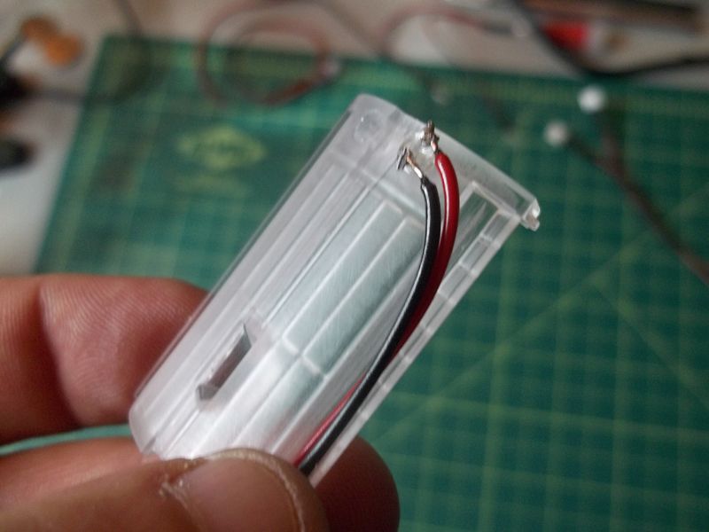
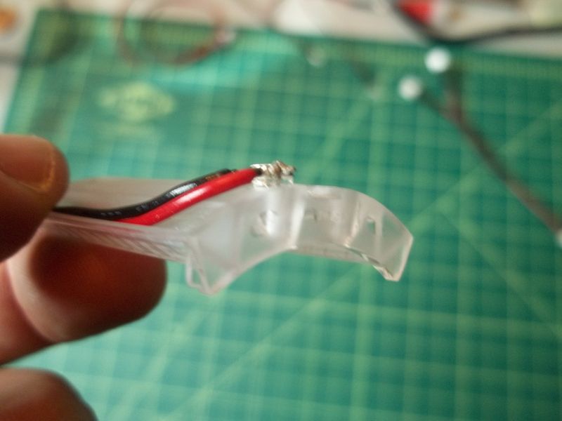
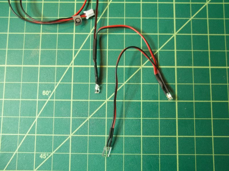
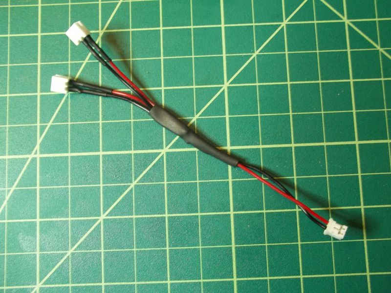
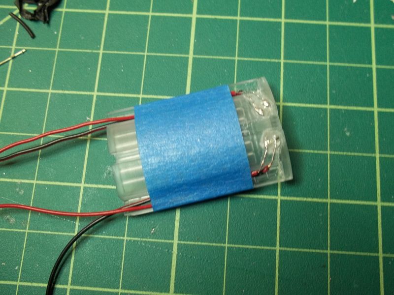
I will also be adding more of the same mini-connectors used in the lighting kit to various places (like the motor and round circuit board wiring) to facilitate easier removal.

I will need to remove those little locking tabs on those connectors. They are a bit difficult to detach once locked. They still fit snug and I could always put a band of heat-shrink around them for insurance.


I’m told I save things way to long. Sometimes, it's a good thing.

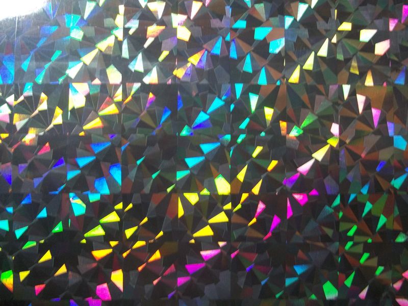
Last Christmas I received a gift in one of those fancy gift bags. I was looking at it and thought, hmmm…

100_0119_zpsfb19f4dd.jpg


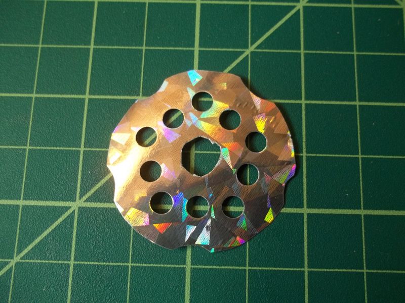
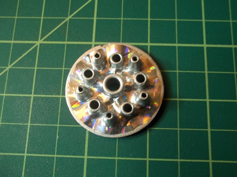
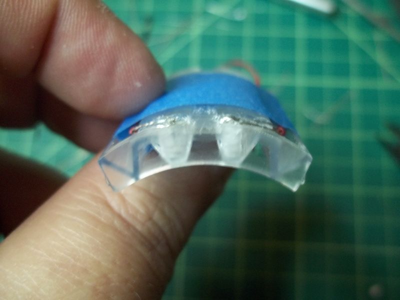
I cut out a shape to fit the back plate for, what I hope, may offer some colorful reflection.

100_0187_zpsd0e95109.jpg


I sprayed the back plate with a few layers of silver lacquer for light blocking and put the piece on. Since my holes were not perfectly positioned, the paper wrinkled up a bit. But, I think that's good.

100_0189_zpsb6dfe678.jpg


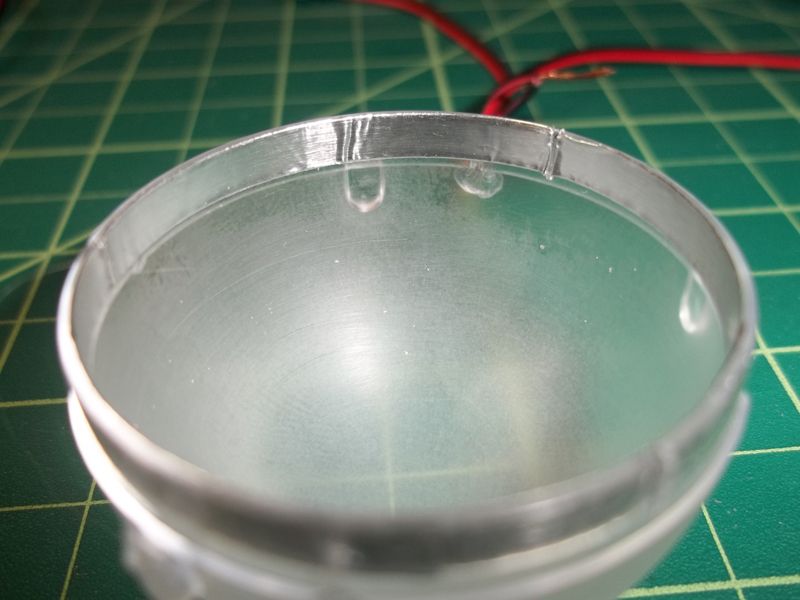
I also put a strip of foil tape around the inner edge of the outer dome to block light from the sides.

100_0200_zps0d858666.jpg


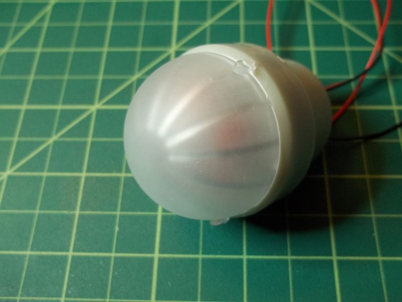
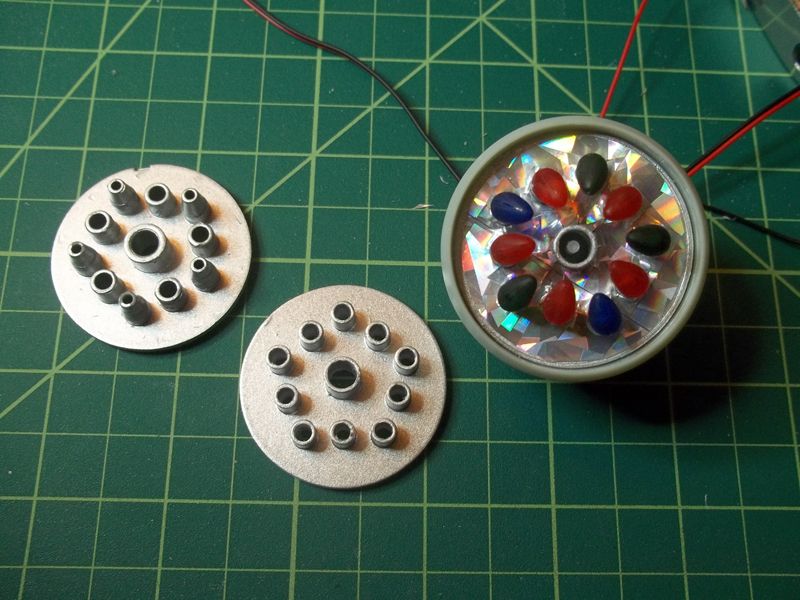
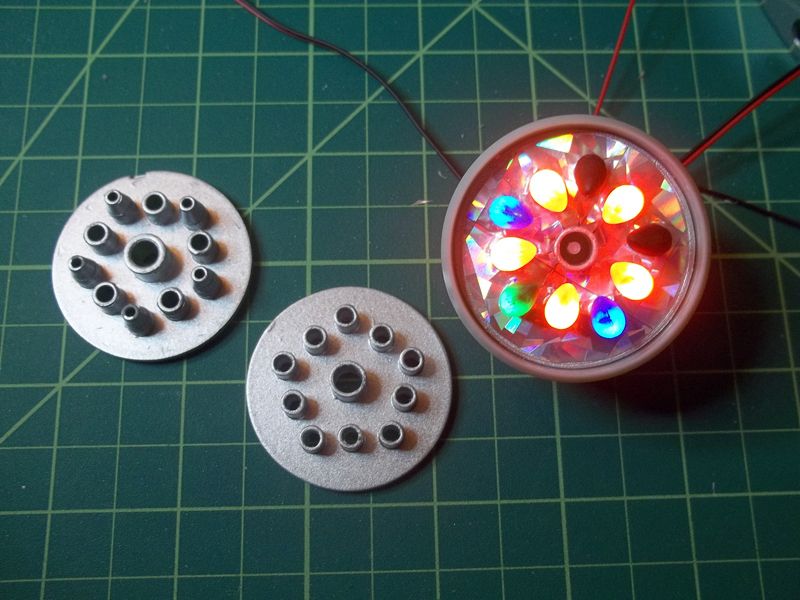
Here is a look at the assembled Collector. I still like the foil tape on the inner dome. The housing is still the unpainted raw plastic.

100_0190_zpse9937662.jpg


I like the overall ‘lights-off’ look. I still have a warped inner dome. I may try an orange-tinted version and see how it looks, too.

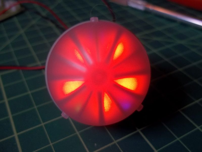
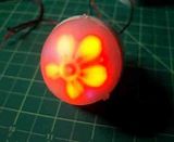
The photo does not even closely represent, but here is a lights on (not spinning) shot.

100_0197_zps633a3284.jpg


My thoughts on the Bussard effect…

It’s pretty cool, but I do have an issue.

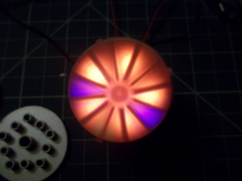
I feel like the colored blinkers are just too small, comparatively dim and focally narrow.

Since the large ‘bulbs’ hang inward, they do cast some light on that foil paper I put in there. Since the colored lights sit directly on top of their shafts, they only cast light straight ahead. None of the colored lights hit the foil.

Since I am making things removable, something I may do later (if not sooner), is make up an alternate back plate that can incorporate ALL large bulbs. Then the colors will be bigger, brighter and reflect like the amber bulbs.

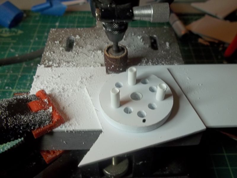
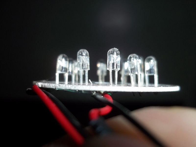
Oh, and due to varied LED heights on the Bussard circuit boards, I had to grind all the bulb shafts down to nubs so they would seat fully, but not so much that they need glue to stay put. They still friction mount.
 
Last edited:
Ok, later came sooner, than… later.

I’ve decided to reconstruct part #42, the Bussard back plate.

I haven’t done any fabrication, but I figure this is a pretty simple part to try.

My aim is to remake the back plate to accept the large ‘bulbs’ all the way around. I want the other colors to be brighter.

But first...

I want to give a shout out to Doug’s Hobbies in Bakersfield, CA.

I didn’t think this town had any (static) modeler support. There are a couple of hobby stores here, but they are more geared to the RC group.

Doug’s does the full range. It will be nice to not always pay shipping and have to wait for supplies. And, I get to support a local business.

Anyway…

I went to Doug’s and picked up some Evergreen.

The original part disc is 1.9mm thick. I had a choice of Evergreen sheet at either 1.5mm or 2mm.

Even though the 2mm is closer, I went with the 1.5mm. I know the outer dome seats in against this part, so I figure thinner better than thicker. I could sand 0.1 off the 2mm, but why go through the extra effort.

I also got some 3/16” tube stock and cut it into 20 9mm lengths.

000_0001_zpsec8c9e9c.jpg


I drew out a pattern using CorelDraw and printed it out.

I taped three sheets of the Evergreen sheet together with the pattern on top.

I started with a pin vise and a large sewing needle to poke holes at the centering intersections of each hole to mark them on the styrene. Then I went to a small bit, that I turned by hand, to make the first pilot holes.

000_0004_zps879b9e13.jpg


Next, I used my Dremel drill press and enlarged the holes to 1/8”.

000_0005_zps0206bcf9.jpg


Then I hit a snag…

The final holes need to be 1/4” for the center and 3/16 for the lights.
These bits won’t fit my Dremel press.

So, I either find someone with a larger press, or I try it using my hand drill.

If I have to use the hand drill, my hope is that at only 1.5mm thick, my ‘straightness’ will not be so critical.

We’ll see.
 
Just a few notes:

In the shuttlebay area, your biggest enemy looks like the wire insulation. For most LEDs, you can use very thin wire. I actually use 30 gauge, and it has thin insulation as well. It fits almost anywhere! While I bought a bunch of spools of various multi-conductor kynar-insulated stuff, look around for "wire-wrap wire." Once a stock item at Radio Shack, it should be readily available from any supply house. The only concern would be current load, and LEDs are such low draw that I've run 10 LEDs from a single wire and don't give it a second thought. BUT, do the proper research to verify the actual safe load for the wire against what the stuff being powered demands. For chassis wiring 30 ga is rated for 0.86 amps. That's a lot of LEDs for the typical draw of 20 mA (0.020 amp). 43 LEDs, if you want to live on the edge (I don't.) But always verify the actual current of the LEDs used because they do vary.

To work with what you have in-place, I'd cut back the insulation so it clears the LED base completely to allow the wire conductor to set completely flush to the LED. A smear of something to insulate and stabilize it, even a reliable tape, and you're done.

I agree with all big lights in the nacelle domes. I'll be going public with my "interpretation" pretty soon. It's beginning to look a lot like Christmas in there!

Don't worry about enlarging your dome base plate holes. I wouldn't think being a few degrees off perpendicular will hurt you.

PS: Wire-wrap wire is great because... you can wire-wrap connections! Instead of soldering. It's a reliable and very convenient way of making connections where space isn't a major issue and requires just a couple basic, inexpensive tools; a wire stripper and a wrapping tool (which looks like it's an alien screwdriver.) Search online about it.
 
Last edited:
I had gone to Radio Shack to look for... stuff.

They didn't have anything higher than 22g wire. I did see the wrapping wire. I thought it was bare wire, so I didn't consider it.

I'm still looking for 30g wire.
 
Well, I went ahead and drilled out the holes with my hand drill.

100_0206_zps7045ccb7.jpg


I put some scrap tube in a few holes to hold the layers together and give me something to hold on to.

Boy, I’m making a mess. I put a sanding drum on my Dremel press and worked the parts around and around until I got the right diameter.

100_0207_zpse464a146.jpg


I put in the tubes and ran some liquid glue around each tube. I had to open up the top of each tube with a 3.5mm bit to accept the plastic ‘bulbs’.

100_0208_zps793879f3.jpg


The local store was out of 1/4” tube for the center hole. They’ll have more on Wednesday.
 
Ok, I think I finally beat the Shuttle Bay lighting into submission.

I drilled out and widened the holes, filed out a trough for the wires, stripped off the insulation from said wires, and filed down the LEDs as far as I dared. And, man, are the connections fragile. Of the original 20 LEDs I bought, I still have 10.

100_0209_zps6cd8089d.jpg

100_0210_zps8e4bdacc.jpg


After painting the part and permanently installing the lights, I will paint on some liquid electrical tape over the wires and LEDs.
 
Wrapping wire is bare. What you want is magnet wire, it has an enamel insulation.

I love seeing folks do their own lighting for this kit, your bussards are looking great.
 
Wrapping wire is bare. What you want is magnet wire, it has an enamel insulation.

Buss wire is bare wire. I've got spools of 30-gauge wrapping wire that are insulated. I guess there might be uninsulated wrapping wire out there...
 
And… back to the Bussards.

My fab’d back plate was stalled waiting for some 9/32 tube (the center) to come in at the hobby shop. They didn’t know such a size existed (Evergreen 229). Their Evergreen display didn’t even have a spot for it.

Here is the original part, my fab’d part and the part installed.

100_0211_zps00928422.jpg


Because my LEDs were widely varied in height, I had to grind down the 'bulb' stems to get them to seat properly.

100_0102_zps23652277.jpg


Now I have the larger ‘bulbs’ all around allowing for more of the flashing colors.

100_0214_zpsf8ce0f2f.jpg

100_0226_zpsa73a08d6.jpg
 
If anyone could help me out, I have a couple of questions concerning painting technicalities.

When I was a kid, I sprayed or airbrushed colors ‘as is’ (no mixes)… just using however much thinner I thought would get it through the airbrush.

Now, I want to be more knowledgeable about what I’m doing.

For instance, I’m looking at painting the Shuttle Bay walls. I have the recommended accent colors which call for a 50/50 mix of MM Neutral Gray and MM Dark Ghost Gray. I also see that Testors suggest a thinner ratio of 3/1 for flat paints.


Here’s my first question:
What methods do you use to measure your mixing ratios?


I had some pipettes that I tried to use, but after the first draw of the paint, you can’t see the level of your next draw until the level is higher than the one before.


Also, I never cared in my younger days, but…


My second question:

Do any of you wear any type of mask when you paint or work with Bondo putty? And, if so, can you make any recommendations?
 
Last edited by a moderator:
3M makes a nice mask for doing work with the sanding.
It has the 2 side cartridges.
I think I picked it up at Home Depot.
 
Can anyone tell me what happened here?

100_0241_zps6b96e784.jpg


This was a first coat of primer.

I shot all three walls of the Bay at the same time. The opposite wall showed minimal signs and the back wall, none at all.

Whatever I did wrong, I don't want to repeat it.

Also...

I tried some Rust-oleum Frosted Glass on a Bussard dome and really liked it.

On the left is my ‘steel wool on the inside/dull coat on the outside’ attempt with the Frosted Glass on the right.

100_0239a_zpsd54dacbf.jpg
 
Last edited:
Back
Top