I’ve been playing around with Shuttle Bay lighting theories.
I have to say, I am wondering if a satisfactory balance of lighting the bay and aft end of the secondary hull can be achieved.
For the bay, getting it look as if the ceiling lights are fully lit does not seem possible. And, with the bay in place, evenly lighting the aft side widows seems difficult.
Just too narrow of spaces in there.
I’m going to give it my best shot at both. But, in the end, I could end up not installing the bay.
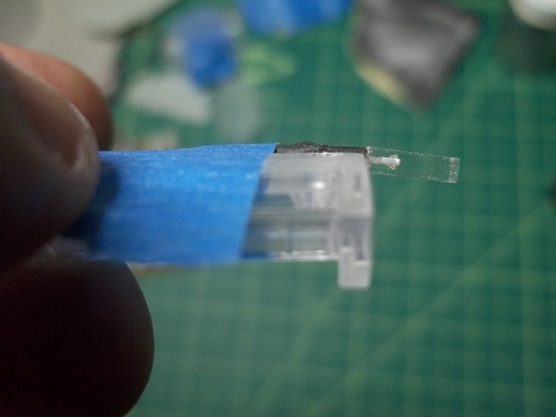
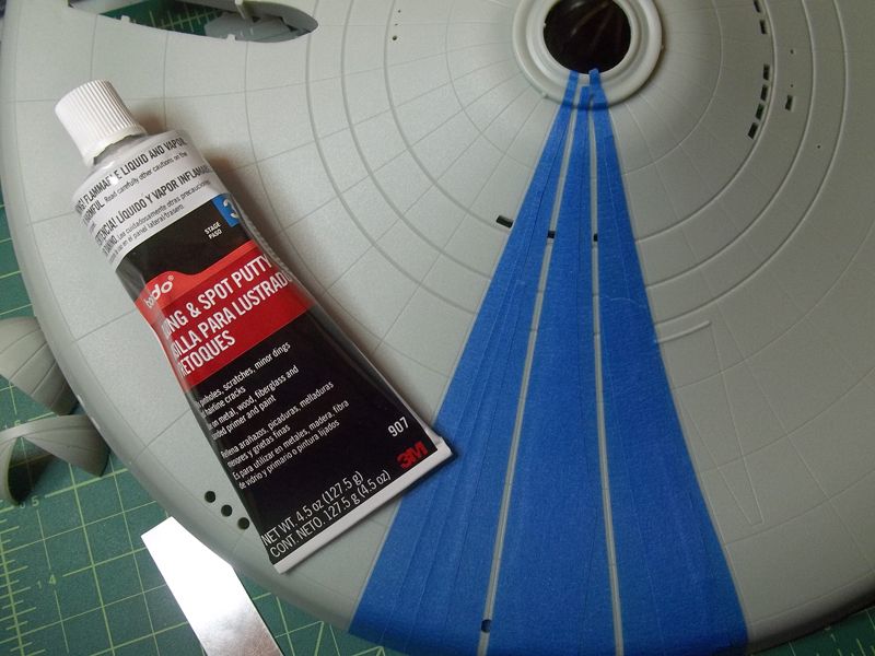
One modification I had to do to the ceiling part:
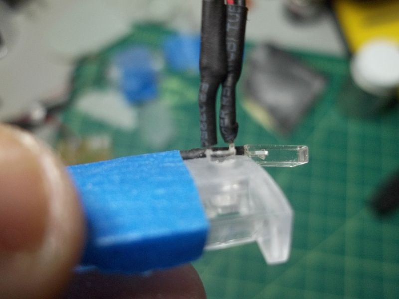
There is a groove in the part that I assume is a channel for the wires leading to the LED for the rear control room. The problem is that the LED leads, with their shrink tubing, is wider and thicker than that groove.
So, I filed it wider and deeper in that area.
Something else I had not thought of is that the wires will be visible through the ceiling lights. If I want to hide them, the center divider will have to be painted wider than accurate.
Something I did find interesting. It could be coincidence, or a lighting idea that didn’t pan out.
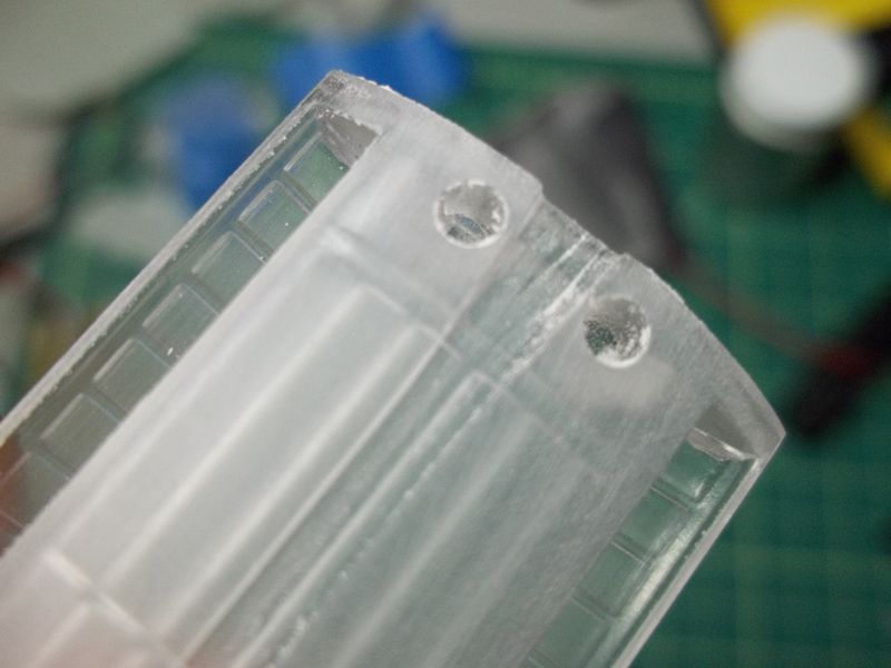
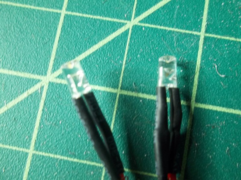
At the aft end of the ceiling part are two holes that are the same size of the ceiling LEDs.
I did a dry fit test with the LEDs in these holes. Though it still didn’t make the ceiling lights look lit, it did a wonderful job of lighting the interior.
I know these ‘bumps’ that I stuck the LEDs in are not considered lighting in the bay architecture, but I thought I could paint the surfaces viewable through the door and leave the far side clear. Then I could paint the ceiling light panels white (thus hiding the wires).
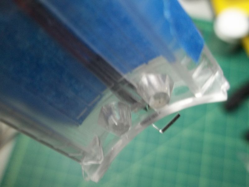
But there’s the catch. Those tight spaces, again.
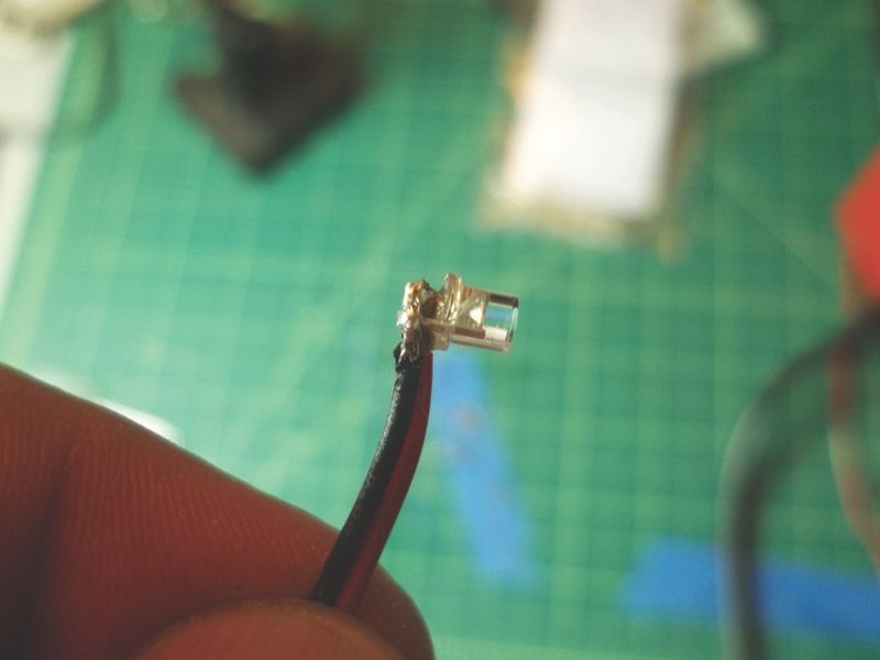
To put the LEDs there, the leads would have to be bent by over 90 degrees, flush to the LEDs, along the ceiling towards those side ‘troughs’, then 90 degrees again along those troughs to run the wires out the back.
That’s the part I don’t think I could do with damaging the LEDs.