Magic of Myth ( MoM ) Luke RotJ Hero ( cave build ) lightsaber research, images, reference, & collaborative model builder's discussion.

Yes, I have some suggestions too.

Painter's tape is great for masking off stuff to protect it - but stick the tape to your shirt or pants first, and rip it off. Less chance of it peeling off paint.

I'm amazed the lacquer didn't mess with the Ace enamel! You can usually lay acrylic over enamel over lacquer but not the other way around. Harder stuff goes on bottom (lacquer) and the solvents are usually stronger or something. but hey, if it worked, don't mess with it, you nailed it!

The real props themselves did not stay pretty either. In the close-ups you can see damage, scratches, etc. so I consider light damage to be authentic :D
It depends on how long the enamel has cured, and especially which brand of lacquer you're using. The old Krylon crystal clear aerosol was a lacquer that was advertised as being able to topcoat anything, as it was SUPER thin and so dried in only a minute or two. Even then, it was possible for it to cause problems if you didn't follow the directions to use multiple thin coats.

Other lacquer aerosols are advertised as being "triple thick" and the can says they take 15 minutes to dry. You'd likely not get away with using those lacquers over enamel, no matter how thin you attempt to spray them or how long the enamel has had to dry.
 
I'm here to cause more trouble. Can those with better castings of the hero answer some questions I have?

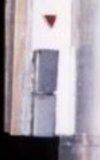
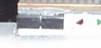
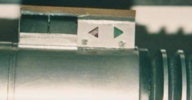
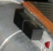
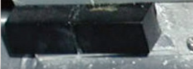
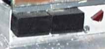
First off, my casting caught the texture of crap all over the left button and the underside of both buttons have striations on them, as if they were cut with a saw. This could change my idea of the source of these, and I can't make the underside out in pictures of the prop. is this another glue smear or is the underneath totally different?

Also I had a really obvious resin bubble in between the buttons on this casting. (2nd Gen from the recent run, forgot the member, but he brought it out of retirement for one more run, brundlefly?) so I decided to pick out the bubble with an X-acto knife and folded sandpaper to see what was under it. Welp...

1) at the top of the buttons, the recess goes all the way back to the box.
2) at the bottom there is actually something there, but it's not flush with the buttons underneath and I don't see any straight lines anywhere, as you'd see with a factory made attached button.
fullsizeoutput_25f1.jpeg
fullsizeoutput_25f3.jpeg
fullsizeoutput_25fe.jpeg
fullsizeoutput_25ff.jpeg


this casting is a little soft in detail (no arrow plate line for example), so it's hard to tell what is original to the first cast or something from the recent pull.

So, it's initially looking like glue in the channel or resin that is covering a spine that's actually there, but it would have to be tiny. The topography here is basically a ramp leading to that curved area at the bottom.
 
Tom, it could also just be the point at which the silicon stopped drippling down. Depending on how viscous the rubber was, at some point, it won't separate and fill any crevasse, it will just cling to itself.
 
Yea, that's right, I've had that happen with Unimax switch molds... so maybe whatever is in there wasn't molded if thats the case?

Also very curious if anyone's casts have those ridges underneath the buttons, as an aside
 
mine does. I’m pretty firmly in my camp of jeweler saw and file marks where they cut the Yuma lever to look like two squared buttons.
 
Yes, I have some suggestions too.

Painter's tape is great for masking off stuff to protect it - but stick the tape to your shirt or pants first, and rip it off. Less chance of it peeling off paint.

I'm amazed the lacquer didn't mess with the Ace enamel! You can usually lay acrylic over enamel over lacquer but not the other way around. Harder stuff goes on bottom (lacquer) and the solvents are usually stronger or something. but hey, if it worked, don't mess with it, you nailed it!

The real props themselves did not stay pretty either. In the close-ups you can see damage, scratches, etc. so I consider light damage to be authentic :D
Yeah I wasn't sure what the ACE paint was made of (acrylic/lacquer/etc.) so it was a risk using lacquer based topcoat. BUT Tamiya's topcoat is a synthetic lacquer and not very hot at all. I spray really thin coats and build them up. I even use it on waterslide decaled models, with no adverse effects. I'm using their modeling tape as well to protect the paint during install. Like you suggested, I've "linted it up" so to speak. But it's a reallllly mild cling to begin with as well. I use it on really delicate papers for fine art purposes and it's gentle as hell.
 
This shot makes me think even the bottom has a groove.
Screen Shot 2021-04-03 at 7.04.48 PM.png


Pics like this make it more confusing
Screen Shot 2021-04-03 at 7.05.11 PM.pngScreen Shot 2021-04-03 at 7.05.32 PM.pngScreen Shot 2021-04-03 at 7.07.29 PM.png

Some other shots, showing how dull and absorbing of light the finish is, not like painted metal but plastic
Screen Shot 2021-04-03 at 7.06.27 PM.pngScreen Shot 2021-04-03 at 7.07.01 PM.png

Screen Shot 2021-04-03 at 7.08.01 PM.png


I may have said it before, I see saw marks in between the buttons on that last photo

I'm going to use another computer with photoshop to see if these are perfectly square
 
I used the 3mm rail as a very general thing to compare to (Edit: I could be wrong about the first one, if we are seeing a hole peek out behind the front button, then it's at least a perfect rectangle. Not square though)

I think the front one is cut crooked on the back, making it tilt forward.
Screen Shot 2021-04-03 at 7.24.12 PM.jpg
Screen Shot 2021-04-03 at 7.25.27 PM.jpg

The back one looks straight but it's not a perfect square.
Screen Shot 2021-04-03 at 7.24.49 PM.jpg
 
img_0249-jpg.jpg

mom-identities04-jpg.jpg

I'm trying to replicate the color of the neck in this shot. It looks slightly redder and darker than the ACE Antique Gold color.
Thinking about applying another coat of copper paint over the ACE Antique Gold and then apply some Tamiya Weathering.
Has anyone tried to replicate the current color of the prop?
 
On my monitor these look exactly like how ACE Antique Gold looks painted on my saber (under incandescent light). But when I take a picture of it with my phone it turns out more yellowish/brassy looking. I guess what I'm trying to say is this paint seems to be tricky for the cameras to capture correctly and it also changes nuances based on the light condition. Add to this monitor gamut and calibration and it's hard to tell 100% what the real color is (I've never seen the prop in person)
 
I'm trying to replicate the color of the neck in this shot. It looks slightly redder and darker than the ACE Antique Gold color.
Thinking about applying another coat of copper paint over the ACE Antique Gold and then apply some Tamiya Weathering.
Has anyone tried to replicate the current color of the prop?

I've personally been using Humbrol 54 (spray can version) and really love the color of it.

It's a bit of a challenging paint in terms of adhesion, but has that look of the original prop where it will look anywhere from a dark gold to a more copper-like tone.

You can see some pictures of mine here (slightly weathered on top of the Humbrol):

 
Hi, I'm curious if anyone tried to identify where the parts for the reveal board came from?

In particular the "big chip" that looks like it is a QFP44 package. I don't really remember something like this in consumer electronics until maybe the early 90s, although a quick search on wikipedia tells me they they were popular in Japan since the late 70s.
But maybe around 1983 there were not that many devices in this package type so it should be possible to identify... I thought it might be a ZIilog Z80 , but around that time it looks they were still made as DIP40.

1625703340844.png


Also what confuses me is why it is considered to be the same board form the "cave build" scene?

Looking at the image below to my eyes at least they are very different circuits ... For example - the chip should occupy the space roughly starting with the tip of the red arrow led to the tip of the green one, and in the cave build there it looks mostly green pcb and some soldier traces

1625704287802.png
 
I believe it’s slices of PCB stacked on top of itself; there are some other photos showing layers.
You’re right it is definitely a 44leg IC and likely from the same board looking at the color but but with the parts collaged together it is hard to identify any sensible enough pattern to ID a specific board. That said I’d also look at boards with very tiny radial dipped tantalum capacitors
 
It's been a while, but I've repaired or modded quite a few guitar effect pedals from that era and from what I remember - exactly this kind of blue color tantalum capacitors were quite common in US made gear (MXR in particular comes to mind) and not at all in the Japanese ones (BOSS, Ibanez). So if the wikipedia article is correct and the chip is Japanese, I also agree it is stacked with other pcb pieces that could be from something else.

There are also some weirdly shaped gold contact surfaces that I've only seen in quartz watches circuits - check this one for example:

1625717792262.png

and some are quite irregularly shaped :

1625717896325.png

that might be another explanation for the stair-like edge of the reveal board

On a side note you can also use these quartz circuits to blink the leds if you connect them to the right places
 
Last edited:
Hi, I'm curious if anyone tried to identify where the parts for the reveal board came from?

In particular the "big chip" that looks like it is a QFP44 package. I don't really remember something like this in consumer electronics until maybe the early 90s, although a quick search on wikipedia tells me they they were popular in Japan since the late 70s.
But maybe around 1983 there were not that many devices in this package type so it should be possible to identify... I thought it might be a ZIilog Z80 , but around that time it looks they were still made as DIP40.

View attachment 1474315

Also what confuses me is why it is considered to be the same board form the "cave build" scene?

Looking at the image below to my eyes at least they are very different circuits ... For example - the chip should occupy the space roughly starting with the tip of the red arrow led to the tip of the green one, and in the cave build there it looks mostly green pcb and some soldier traces

View attachment 1474326
I've spent so many hours in search of this board (and the buttons). Whoever identifies where it came from deserves a medal. I've searched through documents cataloguing 70s/80s electronic company logos, in search of something resembling the pattern on the chip. This led nowhere. Also looking at as many internal images of contemporary electrical items. Nothing. There are a few online microprocessor museums too and I've gone through every image. It really is an enigma. I was hoping that identifying the buttons might lead to identifying the board (or vice-versa).

I'm fairly confident that the board that's seen in the hilt in some of the references is the one in the actual scene though. The chip looks to be in the right place to me.

I think the bright line above the red arrow is the light shining off the pins of the chip:

CARD_CAVE.png
 
This was an older test ; but yes it has definitely survived from filming the cave scene all the way through the table photos to its current state today
2B2AAC8D-A1A7-411B-97C6-195ABA2D271C.jpeg
 

Your message may be considered spam for the following reasons:

If you wish to reply despite these issues, check the box below before replying.
Be aware that malicious compliance may result in more severe penalties.
Back
Top