I like your design a lot and it seems to accurately replicate all the oddities we see in the reference photos! One comment I have is I see in your design a little step on the right side of each wide gold trace, possible an artifact of anti-aliasing, that may need addressing as I think each gold trace should have perfectly straight and parallel sides. Below shows an arrow pointing to what I'm referring to on one of the traces:
http://i17.photobucket.com/albums/b71/cantinadude/slothfurnace_clampcard_05_zpsmzv7rl02.jpg
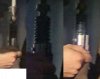
Are you sure you've got the height of the board correct? I agree that the exposed area of the board should be about 0.4" as you suggest, but in your graphic it appears that you have cut off a portion of the bottom of the exposed board visible in the source reference image. This is hard to explain in words, so perhaps this image will help:
http://i17.photobucket.com/albums/b71/cantinadude/slothfurnace_clampcard_05_height_zpswdteunh2.jpg
It looks like the reference image needs to be squashed about 0.05" shorter to fit into the 0.4" visible space between the jaws of the Graflex clamp, which would of course alter the proportions of your design too. Or am I looking at this wrong?
The only other comment I can make is regarding that irregular little shape in the top left corner. Is it possible that it is a round trace termination, similar to what I included in my design graphic below?
http://i17.photobucket.com/albums/b71/cantinadude/Cantina Dudes V2 circuit board 2_zpsxvtlpr5m.jpg
I feel like it could be that the light is reflecting off of the blob of solder and making it look like a little "comma" shape, but might actually be a round trace termination just like all the others on the board. And the bar at the top of the board could very well be another thin silver trace, again something similar to my above design, as opposed to just a thicker silver rectangle.
I'd love to hear your thoughts on this stuff. I'm super stoked to see the best replica of this saber possible!
")

.JPG")
.JPG")