LED Circuit Advice?

Hey,

I'm trying to design an electrical system for a prop laser rifle which includes (among other things) 6 LEDs in a row that light up 1 at a time and stay on to indicate that the 'laser' is charged. Did some google work, but realized I don't quite have the vocabulary to find what it is I need. My electrical knowledge is more geared toward simple home wiring...

Could anyone suggest a supplier that might sell this type of ...LED circuit? Or perhaps there's a website that describes how to build one... either way, I'd love some input. Thanks!
 
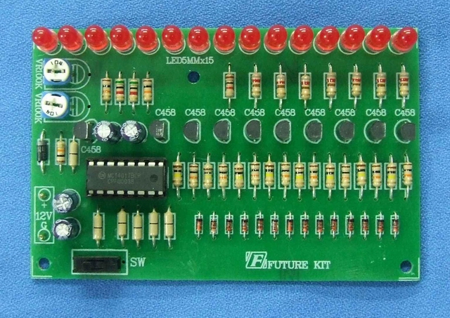
Do you want a pre-made kit or a circuit schematic? Do you want it to slowly go down as you pull the trigger or a static power up and full on? Personally I'd use an LM3914 as I'm more familiar with them. A 4017 would work as well.
 
The PLI is very close. I don't want to measure actual battery charge, but rather simulate a charging cycle. Kind of like this brake light...
led_brake_light_3.jpg

But instead of turning on all at once, the LEDs would light up starting from the left...
100000
110000
111000
111100
111110
111111 <- and hold with all of them on.

I'd be happy buying a chip (driver?) and adding some LEDs to it, if that's a possibility.

Maybe there's a workaround with variable resistors or something... :confused

Thanks for the links!
 
I'll think a bit on this,
but a 4017 is coming to mind... that might work.
oh, but you would have to have a filp flop after it to keep the lights on, then a reset switch (Gun trigger) would clear the whole thing.
 
Last edited:
What is your budget? I can make up a quicky circuit to do that but like every one off it won't be as cheap as finding a production or off the shelf item...

If you want it manual where you crank a pot to walk up the lights, look at the LM3914, short and simple... If you want it automated it will take a little more...
 
Last edited:
the 4017 is a counter so with every clock signal the next led is on so this is not the right effect http://www.doctronics.co.uk/4017.htm#operation

http://www.elecfree.com/electronic/running-lights-by-lm555-4017/
or use a blinking led instead of the 555

with some tricks you can get the led to light up use transistors and wire the uper number to the lowers so when 3 lights up 1 and 2 light up too i think resistors would be the best way to switch them on i dont know how many led the 4017 could drive.

and another 2 transistor as opener so the clock signal can be cut and the lights stay on.

you can do more if you want so when you push a button you can stop the charging effect (if you connect the transistor "opener" with a button


but the best way would be to get a tiny and make a small program for it.
 
Last edited:
Let me try to understand this, but wrong me if I am right:

You want to pull the trigger, and the six LEDs would come on one by one (1,2,3,4,5,6), until its "full" and when you release the trigger, it falls back very fast (6,5,4,3,2,1)

If that is the case, may I point you towards the direction of a microcontroller chip which usually only requires (apart from programming tools) the LEDs, current limiting resistors and a voltage regulator. :)
 
Glad someone else finally suggested it. Granted, the builder himself admitted he didn't have the knowledge to do such a circuit; but with all the advice I was reading, I wondered if anyone was going to suggest just programming a micro. :)


ATM
ShackMan
 
I wondered if anyone was going to suggest just programming a micro. :)

Well there is no just programming a micro ;) Generally you need at least basic programming skills and some sort of programmer, this can add substantially to the cost vs using discrete components...

For a simple circuit like this a micro is certainly IMO today's best option, it can result in a very compact and easy to modify circuit... But for a simple one off circuit like this is might be more 'affordable' to simply have someone make up a micro based circuit vs assembling and getting your mind wrapped around designing a micro based circuit... It takes away from the DIY satisfaction, but that is all a matter of personal preference, thus the reason I originally asked on the budget, if $25ish is in the range I could provide a turnkey custom specified solution... It's certainly cheaper to find an over the counter kit and bash it to work or DIY if you have the knowledge in many cases...
 
Everyone jumps to programing a microcontroller chip

a 4017 IC is only $2.00

But the 4017 can't do the job alone, it needs supporting circuitry aka the pulse signal...

A pic12F675 can be had for $1.50 and can be a single chip solution if you want to get down and dirty... And it's half the size of the 4017 already...

Using a micro is no different then using a 4017, you are still using an IC and not discrete components... The only difference is you are using 1960/70s IC tech vs modern IC tech...
 
Yup. Was gonna say, I paid $2.68 for my last 16F628s. 18 pin chip that does all you need and more for this circuit. Different strokes ... ;)


ATM
ShackMan
 
Use the right Pic (something like a 16f630) and you can get out for under $2.00 (not including the battery, leds, and led resistors).
 
A PIC12F675, 3 resistors (or 6 depending on how you wire and code it) and 6 standard LEDs is still at that $2 mark and it's a complete circuit once you code it... All in a compact 8 pin IC footprint... I would personally add a cap and voltage regulator to the circuit but it's not 'necessary' to get the circuit up and running and I would even add the cap and regulator to the 4017 circuit so it's really null...

If you were to use a 4017 (BTW if you want the LEDs to latch and stay lit as they climb you would be better off with a 4015), you would need a clock circuit as well, the 4017 is a 16 pin chip, if you use a 555 timer that is another 8 pins, and the 555 requires 2 or 3 support components (resistors and a cap) for more 'pins' pushing the total to about 30 pins... In the end the circuit is 3 or 4 times larger... The above pictured circuit uses 2 transistors, 2 caps and some resistors instead of a 555 still lots of extra parts...

The 4000 series chips are wonderful and they are very well instilled in electronics education and old school thought, but IMO lets face it it's not the 1970s any longer... Not saying there is anything wrong with using 1970s tech but I'm sure as hell not going to limit myself to 1970s tech while there is a whole new world of electronics out there... The reason everyone tosses a micro at the job is simple, they get it done and usually at a lower parts count, and they are a lot more configurable...
 
Last edited:
Back
Top