xl97
Master Member
they are probably wired differently..?
I wouldnt suggest using them (as discussed in this thread already)
regular, individual leds..or a purpose made eye pcb would be best..
and (again) using 9v also isnt recommended...
5 x alkaline to get the voltage difference a bit closer to the board/components needs..without too much being burned off as heat.
or
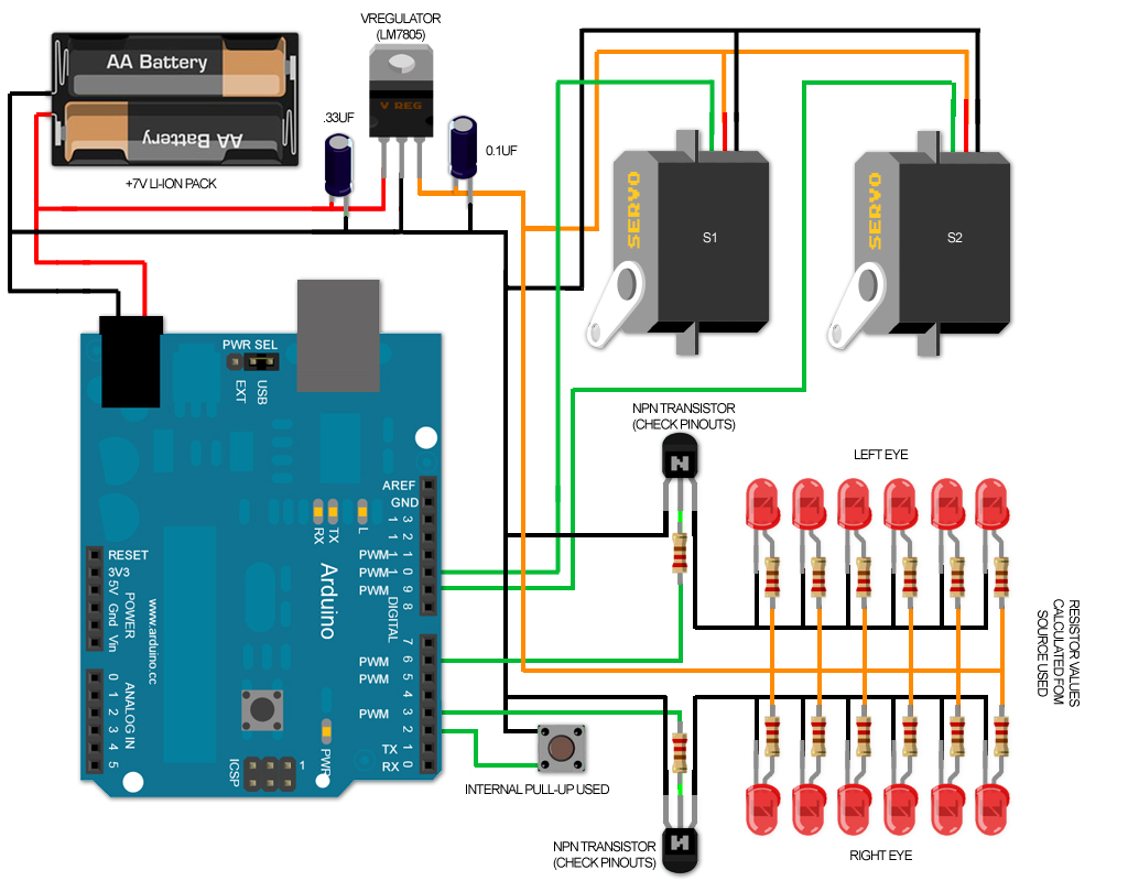
2 x 3.7v li-ions in a 7.4v pack would be best.. IMHO..
I wouldnt suggest using them (as discussed in this thread already)
regular, individual leds..or a purpose made eye pcb would be best..
and (again) using 9v also isnt recommended...
5 x alkaline to get the voltage difference a bit closer to the board/components needs..without too much being burned off as heat.
or
2 x 3.7v li-ions in a 7.4v pack would be best.. IMHO..
")