You are using an out of date browser. It may not display this or other websites correctly.
You should upgrade or use an alternative browser.
You should upgrade or use an alternative browser.
Iron man motorised faceplate electronics tutorial!!!
- Thread starter 7sinzz
- Start date
Hi all.
Getting much closer in finishing the mechanism for my helmet.
Electronics are still getting on my nerves.. not my specialism so 2 speak.
Most of it works but i cant seem to figure out how to get my electronics to work with an external power source.
My setup is really like in the first post. now with the breadboard and my arduino nano attached..
With the usb from my Imac to the NANO, the 2 servos work perfectly directly of the Nano 5V output.
I first tried to attach a 9v battery to the Vin of the Nano. and a 6V (4AA) batterypack to the servos. Did not work. Switch didnt work, light did not came on, and on of the servos fried! (yes i also tried 4 rechargable AA = 4,8V). NO Working servos.
Then i yesterday came across a GP portable USB charger, that gives 5V and 1000 Mah output. Same as a PC. But still didnt work. light of the NAno was on but no servo action and light action. I really thought this little thing was the perfect solution. WHERE DOES THIS GO WRONG?
Also i have little trouble with the light. I first tried LEds in serial, but for best light result i want to attach a 9V battery to the LED strips i bought. They light up really nice. The only problem i have now... How to attach this to the NANO to get the blinking and fading effect. Will some kind of Relais do the trick? S/+/-?
Any help would be VERYYYYY welcome.
Thanks guys!
1º of all, pictures tells more than words, so, take some pictures of your setup.
2º: I don't know what servos you are using to give you any advice, mos of them works great between 4.8 and 6V, like i said most of them, not all of them, you need to give more information about what you are using.
3º: I don't Know what version of the nano you are using, there are 3V and 5V versions, need more information
4º: you never mentioned if you connected all the GND's together, thats a important step!
5º: to keep the fade effect functional you will need to use some transistors.
JayCVenlo
Sr Member
1. I'll post it as soon as i have the time. My setup is basically the same as in the first thread.
2. Servos are tower pro mg90s. Work on 4.6v up to 6v
3. Nano v3
4. Al grounds are connected to the nano ground
5. My knowledge for transistors is probably to low to figure it out myself.
I am a designer not a electrician
2. Servos are tower pro mg90s. Work on 4.6v up to 6v
3. Nano v3
4. Al grounds are connected to the nano ground
5. My knowledge for transistors is probably to low to figure it out myself.
I am a designer not a electrician
Ok after reading all 400 pages of this thread... Lol... There is so much info my head is starting to spin with so many ideas... I wanted to chime in and make a list of what I wanted to make on my helmet... And see if someone(s) would be able to help me put a list together of everything I would need, because I am new to all of this... So here goes...
I want the face and jaw to open and close, the eyes to light up and would love to have Jarvis initializing setup, and talking to me... I am looking at installing video glasses and a pinhole camera like I have seen a few peoe on this thread already talk about... I am pretty sure the electronics for that I can handle, but as far as for the rest... Well I need some help... And how is everyone making the helmet open and close once it is completed... All I have seen is the push button on the Arduino board...
I want the face and jaw to open and close, the eyes to light up and would love to have Jarvis initializing setup, and talking to me... I am looking at installing video glasses and a pinhole camera like I have seen a few peoe on this thread already talk about... I am pretty sure the electronics for that I can handle, but as far as for the rest... Well I need some help... And how is everyone making the helmet open and close once it is completed... All I have seen is the push button on the Arduino board...
JayCVenlo
Sr Member
Ok after reading all 400 pages of this thread... Lol... There is so much info my head is starting to spin with so many ideas... I wanted to chime in and make a list of what I wanted to make on my helmet... And see if someone(s) would be able to help me put a list together of everything I would need, because I am new to all of this... So here goes...
I want the face and jaw to open and close, the eyes to light up and would love to have Jarvis initializing setup, and talking to me... I am looking at installing video glasses and a pinhole camera like I have seen a few peoe on this thread already talk about... I am pretty sure the electronics for that I can handle, but as far as for the rest... Well I need some help... And how is everyone making the helmet open and close once it is completed... All I have seen is the push button on the Arduino board...
Dont get ahead of your self.
Just getting the arduino and servos running on an external power source is one hel of job to do.
Refering to de jarvis sound.. I want it to.
What I did now:
I bought the inside of a wishing card. you can get them, to record your own 8 second sample. The speaker wasnt to good so i bought a different one. Now i just have to figure out if i want to attach the chip directly to the Arduino or not, or if i wal just use the switch on the wishcard chip. Because i have no idea how to connect this thing to the arduino.
Good luck on your project
JayCVenlo
Sr Member
Would this be usefull as a external powersource for the Arduino Nano...
USB Battery Box -Convert 4 AA Batteries to USB Port Power
The GP portable charger i bought didnt work. Maybe that was for charging only and this is an external power source.
Or do the things work the same?
USB Battery Box -Convert 4 AA Batteries to USB Port Power
The GP portable charger i bought didnt work. Maybe that was for charging only and this is an external power source.
Or do the things work the same?

JayCVenlo
Sr Member
Well I have a while before I begin diving into the electronics... I have to build my suit first... But I did get an awesome Father's Day present to help me along with that... It's a Silhouette Cameo.... And can be used with Pepakura...View attachment 199458
Damn, that ***** makes life easy!!! haha. Good luck with the build. pepakura is a long build but a precise one.
KamikazeHamster
New Member
I was helping my boyfriend build his suit and had so much fun I'm making my own. This thread has been a lifesaver! And now the servos and everything work; we just need to figure out a decent hinge system, but that seems much more user friendly to me than the coding was.
TattooMike
New Member
I was helping my boyfriend build his suit and had so much fun I'm making my own. This thread has been a lifesaver! And now the servos and everything work; we just need to figure out a decent hinge system, but that seems much more user friendly to me than the coding was.
Good luck! The hinge system (to me) is much easier. With that being said the hinge system will definitely depend on the helmet you are using, size, type, etc. I know personally I have 3 MRK 3 helmets, and a 42 and the hinge systems will all have to be different. I was thinking of making a universal hinge system that could be adjusted with thumb screws for position of axis points. That would make it easier to use on almost every helmet. I build old school "bobber" motorcycles and got the idea to do something like that from the rear swing arm adjustments on some of the old harleys. I will update if I come up with something that works on all of mine.
JayCVenlo
Sr Member
Guys i have some great news what would be maybe usefull for everone who uses a chip with USB connection. I was talking about trying to use a GP external battery pack/charger. It didn't work. But i rechecked every connection on my breadboard, now plugged in the GP tot the USB input on my Arduino Nano and it works, INCLUDING the servos directly connected to the NANO.
So instead of 2 ****ty battery packs (9V and 4.8V).. i have on great looking power source that is easy to charge.
Here is the setup:

ONLY one BIG problem. Whenn the helmet is in OPEN position. So that means OFF. after a few minutes the GP and NANO shutt off.. because the GP probably sees ow nothing is happening, no need to give power.
Is there away to programm the code so that the NANO keeps asking for power? Or do i have to buy a different charger with a continious on/of switch?
This one works by pressing the button > turns on > automatic shut down wen not needed.
Love to hear some comments and suggestions.
ps. Just resprayed the faceplate... lovin the result!
So instead of 2 ****ty battery packs (9V and 4.8V).. i have on great looking power source that is easy to charge.
Here is the setup:
ONLY one BIG problem. Whenn the helmet is in OPEN position. So that means OFF. after a few minutes the GP and NANO shutt off.. because the GP probably sees ow nothing is happening, no need to give power.
Is there away to programm the code so that the NANO keeps asking for power? Or do i have to buy a different charger with a continious on/of switch?
This one works by pressing the button > turns on > automatic shut down wen not needed.
Love to hear some comments and suggestions.
ps. Just resprayed the faceplate... lovin the result!
Guys i have some great news what would be maybe usefull for everone who uses a chip with USB connection.
As a "Electrician", i need to say that is not that useful, somethings are not OK with your electrical setup.
I'm doing this so you can learn some more on this field.
How the Arduino works in its misterious ways:
The Arduino was designed as a smart control platform. Not to provide power to loads, with that in mind,
the Arduino have a max output of 40mA (0.04A) limited by the micro-controller, anything beyond this will work for a short period of time, but it also will damage the micro-controller very quickly due overload and overheating.
----------------------------------------------//---------------------------------------
The servos magic:
In the spoiler you can see the "universal" specs of 9G servos (the ones you are using)
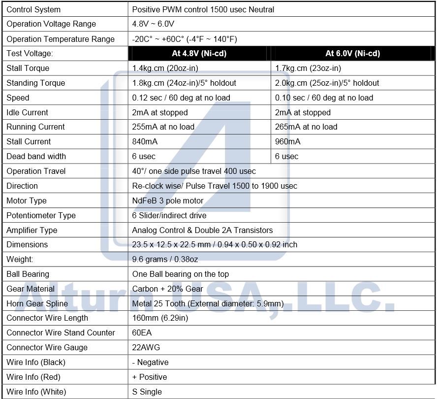
looking at the datasheet we can see that the Idle current is 2mA, that's totally compatible with the Arduino output, but the running current is 255mA in the best scenario. This is 638% over the Arduino output limit, it will work for a few, but over the time it will damage your Arduino board.
To prevent that, you need to run your servos with a dedicated battery pack, preferentially a regulated Vout one.
----------------------------------------------//---------------------------------------
Bling, Bling:
Lets talk about the LED now, it is working nice cause you only have 1 LED on the board, this one LED is just using 20mA, and this is fine for the arduino, since it can handle 40mA on the output, but, put 2 more in series and you will be in trouble, like the servos you need to run them on a dedicated battery pack.
The right way to apply the LEDs this project is to put them in parallel and connects them to the regulated 5V battery pack, each led with its individual resistor to limit the current.
If you want to keep the fade effect, it will be necessary to use transistors, which operate basically as a relay, but at the same time has the ability to limit the current on the output, using almost no current on its control pin.
----------------------------------------------//---------------------------------------
The sorcery of the single battery pack:
how to use a single battery pack for the whole circuit?
you will need to use a nice battery pack, with 2000mA/h or more, with 7.4 ~ 9V, and regulate the output for your needs.
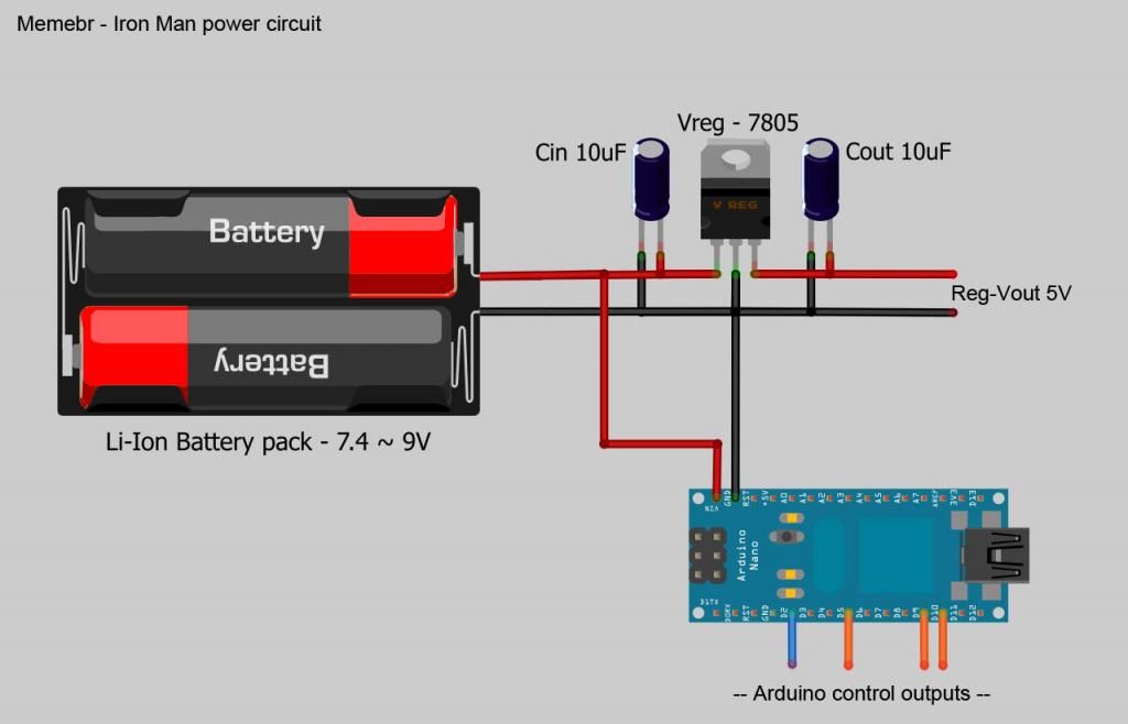
You can see in the image that we have a single battery pack, supplying power to the Arduino and to a regulated 5V load at the same time, saving the Arduino from the effort of providing current to the servos and protecting it, this way you are making sure that the Arduino board is working inside the current limitations. (also, you can see that all the GND's are connected together, the battery pack GND, the Arduino GND, the regulator GND and the load GND)
I hope this can help you and perhaps others who are having the same problems.
Last edited:
msleeper
Sr Member
There's a lot of info on setting up the electronics and the Arduino code, which is awesome. But has anyone made available their hinge designs in detail? The videos that Demolition put up are totally awesome but it's hard to determine the actual shape and scale of the hinge arms.
Last edited by a moderator:
xl97
Master Member
thats very hard to 'blanket' so it works/fits for everyone...
people are using different buckets/helmets.. different casts, different models, different sizes..etc..
some are doing top hinges, some side.. some people using gears....
use some cardboard to mock up the size and shape that works best for you..using the video as a 'guide' only..
people are using different buckets/helmets.. different casts, different models, different sizes..etc..
some are doing top hinges, some side.. some people using gears....
use some cardboard to mock up the size and shape that works best for you..using the video as a 'guide' only..
msleeper
Sr Member
No no I realize that. I don't expect there to be a universal, one-size-fits-all setup. Let me rephrase the question: Does anyone have more archival photos of their hinge components? I understand the concept behind the arms and their linkages, I was just hoping for more and better photos to draft my own designs from.
Djstorm100
Active Member
As a "Electrician", i need to say that is not that useful, somethings are not OK with your electrical setup.
I'm doing this so you can learn some more on this field.
How the Arduino works in its misterious ways:
The Arduino was designed as a smart control platform. Not to provide power to loads, with that in mind,
the Arduino have a max output of 40mA (0.04A) limited by the micro-controller, anything beyond this will work for a short period of time, but it also will damage the micro-controller very quickly due overload and overheating.
----------------------------------------------//---------------------------------------
The servos magic:
In the spoiler you can see the "universal" specs of 9G servos (the ones you are using)
looking at the datasheet we can see that the Idle current is 2mA, that's totally compatible with the Arduino output, but the running current is 255mA in the best scenario. This is 638% over the Arduino output limit, it will work for a few, but over the time it will damage your Arduino board.
To prevent that, you need to run your servos with a dedicated battery pack, preferentially a regulated Vout one.
----------------------------------------------//---------------------------------------
Bling, Bling:
Lets talk about the LED now, it is working nice cause you only have 1 LED on the board, this one LED is just using 20mA, and this is fine for the arduino, since it can handle 40mA on the output, but, put 2 more in series and you will be in trouble, like the servos you need to run them on a dedicated battery pack.
The right way to apply the LEDs this project is to put them in parallel and connects them to the regulated 5V battery pack, each led with its individual resistor to limit the current.
If you want to keep the fade effect, it will be necessary to use transistors, which operate basically as a relay, but at the same time has the ability to limit the current on the output, using almost no current on its control pin.
----------------------------------------------//---------------------------------------
The sorcery of the single battery pack:
how to use a single battery pack for the whole circuit?
you will need to use a nice battery pack, with 2000mA/h or more, with 7.4 ~ 9V, and regulate the output for your needs.
http://i3.photobucket.com/albums/y87/oozi/powercircuit_zpsb3eb6640.jpg
You can see in the image that we have a single battery pack, supplying power to the Arduino and to a regulated 5V load at the same time, saving the Arduino from the effort of providing current to the servos and protecting it, this way you are making sure that the Arduino board is working inside the current limitations. (also, you can see that all the GND's are connected together, the battery pack GND, the Arduino GND, the regulator GND and the load GND)
I hope this can help you and perhaps others who are having the same problems.
You are using two CON 10uf ..one is for the board if it gets "hungry" and same with the servo so the voltage spike is kept at a min.? Never seen a CIN CAP that's why I'm asking. I never though I would love this much lol Thanks guys as always.
Similar threads
- Replies
- 1
- Views
- 311
- Replies
- 1
- Views
- 456
- Replies
- 2
- Views
- 546